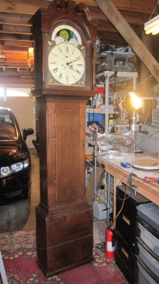
Frankly, we let out a yelp of despair when we read this in the tip line “Antique Grandfather clock with Arduino insides“! But before you too roll your eyes, groan, or post snark, do check out [David Henshaw]’s amazing blog post on how he spent almost eight months working on the conversion.
Before you jump to any conclusions about his credentials, we must point out that [David] is an ace hacker who has been building electronic clocks for a long time. In this project, he takes the antique grandfather clock from 1847, and puts inside it a new movement built from Meccano pieces, stepper motors, hall sensors, LEDs, an Arduino and lots of breadboard and jumper wires while making sure that it still looks and sounds as close to the original as possible.
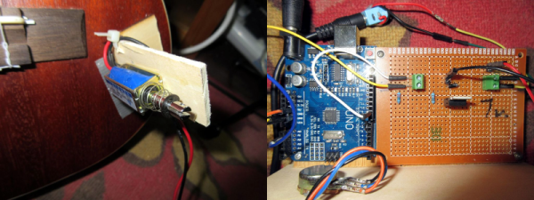
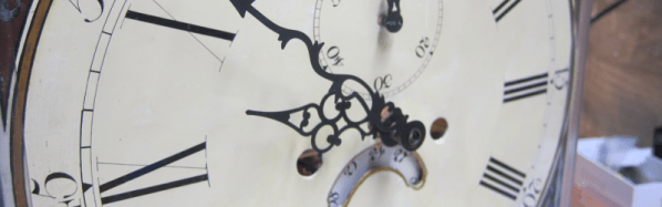
 He starts off by building a custom electro-mechanical clock movement, and since he’s planning as he progresses, meccano, breadboard and jumper wires were the way to go. Hot glue helps preserve sanity by keeping all the jumper wires in place. To interface with all of the peripherals in the clock, he decided to use a bank of shift registers driven from a regular Arduino Uno. The more expensive DS3231 RTC module ensures better accuracy compared to the cheaper DS1307 or similar clones. A bank of RGB LEDs acts as an annunciator panel inside the clock to help provide various status indications. The mechanical movement itself went through several iterations to get the time display working with a smooth movement of the hands. Besides displaying time, [David] also added a moon phase indicator dial. A five-rod chime is struck using a stepper motor driven cam and a separate solenoid is used to pull and release three chime hammers simultaneously to generate the loud gong sounds.
And here’s the amazing part – he did all of this before laying his hands on the actual grandfather clock – which was shipped to him in California from an antique clock specialist in England and took two months to arrive. [David] ordered just the clock housing, dial/face and external parts, with none of the original inner mechanism. Once he received it, his custom clock-work assembly needed some more tweaking to get all the positions right for the various hands and dials. A clock like this without its typical “ticktock” sound would be pretty lame, so [David] used a pair of solenoids to provide the sound effect, with each one being turned on for a different duration to produce the characteristic ticktock.
At the end of eight months, the result – christened Judge – was pretty satisfying. Check the video below to judge the Judge for yourself. If you would like to see some more of [David]’s clockwork, check out Dottie the Flip Dot Clock and A Reel to Reel Clock.
Continue reading “Modernizing A 170 Year Old Antique Grandfather Clock” →