Parametric Design Process Produces Unique Speakers

When building one-off projects, it’s common to draw up a plan on a sheet of paper or in CAD, or even wing it and hope for the best outcome without any formal plans. Each of these design philosophies has its ups and downs but both tend to be rigid, offering little flexibility as the project progresses. To solve this, designers often turn to parametric design where changes to any part of the design are automatically reflected throughout the rest, offering far greater flexibility while still maintaining an overall plan. [Cal Bryant] used this parametric method to devise a new set of speakers for an office, with excellent results.

The bulk of the speakers were designed with OpenSCAD, with the parametric design allowing for easy adjustments to accommodate different drivers and enclosure volumes. A number of the panels of the speakers are curved as well, which is more difficult with traditional speaker materials like MDF but much easier with this 3D printed design. There were a few hiccups along the way though; while the plastic used here is much denser than MDF, the amount of infill needed to be experimented with to achieve a good finish. The parametric design paid off here as well as the original didn’t fit exactly within the print bed, so without having to split up the print the speakers’ shape was slightly tweaked instead. In the end he has a finished set of speakers that look and sound like a high-end product.

There are a few other perks to a parametric design like this as well. [Cal] can take his design for smaller desk-based speakers and tweak a few dimensions and get a model designed to stand up on the floor instead. It’s a design process that adds a lot of options and although it takes a bit more up-front effort it can be worth it while prototyping or even for producing different products quickly. If you want to make something much larger than the print bed and slightly changing the design won’t cut it, [Cal] recently showed us how to easily print huge objects like arcade cabinets with fairly standard sized 3D printers.

Most Powerful Laser Diodes, Now More Powerful

Many hobbies seem to have a subset of participants who just can’t leave well enough alone. Think about hot rodders, who squeeze every bit of power out of engines they can, or PC overclockers, who often go to ridiculous ends to milk the maximum performance from a CPU. And so it goes in the world of lasers, where this avalanche driver module turns Nichia laser diodes into fire-breathing beasts.

OK, that last bit might be a little overstated, but there’s no denying the coolness of what laser jock [Les Wright] has accomplished here. In his endless quest for more optical power, [Les] happened upon a paper describing a simple driver circuit that can dump massive amounts of current into a laser diode to produce far more optical power than they’re designed for. [Les] ran with what few details the paper had and came up with a modified avalanche driver circuit, with a few niceties for easier testing, like accommodation for different avalanche transistors and a way to test laser diodes in addition to the Nichia. He also included an onboard current sensing network, making it easy to hook up a high-speed oscilloscope to monitor the performance of the driver.

For testing, [Les] used a high-voltage supply homebrewed from a Nixie inverter module along with a function generator to provide the pulses. The driver was able to push 80 amps into a Nichia NUBM47 diode for just a few nanoseconds, and when all the numbers were plugged in, the setup produced about 67 watts of optical power. Not one to let such power go to waste, [Les] followed up with some cool experiments in laser range finding and dye laser pumping, which you can check out in the video below. And check out our back catalog of [Les]’ many laser projects, from a sketchy tattoo-removal laser teardown to his acousto-optical filter experiments. Continue reading “Most Powerful Laser Diodes, Now More Powerful”

Reverse Engineering A Keyboard Driver Uncovers A Self-Destruct Code

Should you be able to brick a keyboard just by writing a driver to flash the lights on it? We don’t think so either. [TheNotary] got quite the shock when embarking on a seemingly straightforward project to learn C++ on the x86-64 architecture with Windows and sent it straight to Silicon Heaven with only a few seemingly innocent USB packets.

The project was a custom driver for the XVX S-K80 mechanical keyboard, aiming to flash LED patterns across the key LEDs and perhaps send custom images to the integrated LCD. When doing this sort of work, the first thing you need is the documentation of the communications protocols. Obviously, this was not an option with a closed-source project, so the next best thing is to spy on the existing Windows drivers and see how they worked. Using Wireshark to monitor the USB traffic whilst twiddling with the colour settings, it was clear that communications were purely over HID messages, simplifying subsequent analysis. Next, they used x32dbg (now x64dbg, but whatever) to attach to the existing driver process and trap a few interesting Windows system calls. After reading around the Windows API, a few candidate functions were identified and trapped. This gave them enough information to begin writing code to reproduce this behaviour. Then things got a bit odd.

Continue reading “Reverse Engineering A Keyboard Driver Uncovers A Self-Destruct Code”

An Open Source 6kW GaN Motor Controller

We don’t know how you feel when designing hardware, but we get uncomfortable at the extremes. High voltage or current, low noise figures, or extreme frequencies make us nervous.  [Orion Serup] from CrabLabs has been turning up a few of those variables and has created a fairly beefy 3-phase motor driver using GaN technology that can operate up to 80V at 70A. GaN semiconductors are a newer technology that enables greater power handling in smaller packages than seems possible, thanks to high electron mobility and thermal conductivity in the material compared to silicon.

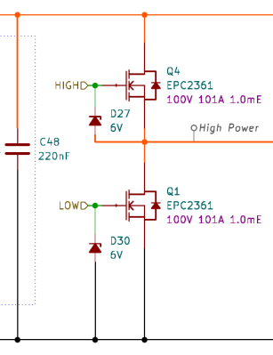
The KiCAD schematic shows a typical high-power driver configuration, broken down into a gate pre-driver, the driver itself, and the following current and voltage sense sub-circuits. As is typical with high-power drivers, these operate in a half-bridge configuration with identical N-channel GaN transistors (specifically part EPC2361) driven by dedicated gate drivers (that’s the pre-driver bit) to feed enough current into the device to enable it to switch quickly and reliably.

The design uses the LM1025 low-side driver chip for this task, as you’d be hard-pushed to drive a GaN transistor with discrete components! You may be surprised that the half-bridge driver uses a pair of N-channel devices, not a symmetric P and N arrangement, as you might use to drive a low-power DC motor. This is simply because, at these power levels, P-channel devices are a rarity.

Why are P-channel devices rare? N-channel devices utilise electrons as the majority charge carrier, but P-channel devices utilise holes, and the mobility of holes in GaN is very low compared to that of electrons, resulting in much worse ON-resistance in a P-channel and, as a consequence, limited performance. That’s why you rarely see P-channel devices in a circuit like this.

Continue reading “An Open Source 6kW GaN Motor Controller”

Unusual Tool Gets An Unusual Repair

In today’s value-engineered world, getting a decade of service out of a cordless tool is pretty impressive. By that point you’ve probably gotten your original investment back, and if the tool gives up the ghost, well, that’s what the e-waste bin is for. Not everyone likes to give up so easily, though, which results in clever repairs like the one that brought this cordless driver back to life.

The Black & Decker “Gyrodriver,” an interesting tool that is controlled with a twist of the wrist rather than the push of a button, worked well for [Petteri Aimonen] right up until the main planetary gear train started slipping thanks to stripped teeth on the plastic ring gear. Careful measurements of one of the planetary gears to determine parameters like the pitch and pressure angle of the teeth, along with the tooth count on both the planet gear and the stripped ring.

Here, most of us would have just 3D printed a replacement ring gear, but [Petteri] went a different way. He mentally rolled the ring gear out, envisioning it as a rack gear. To fabricate it, he simply ran a 60° V-bit across a sheet of steel plate, creating 56 parallel grooves with the correct pitch. Wrapping the grooved sheet around a round form created the ring gear while simultaneously closing the angle between teeth enough to match the measured 55° tooth angle in the original. [Petteri] says he soldered the two ends together to form the ring; it looks more like a weld in the photos, but whatever it was, the driver worked well after the old plastic teeth were milled out and the new ring gear was glued in place.

We think this is a really clever way to make gears, which seems like it would work well for both internal and external teeth. There are other ways to do it, of course, but this is one tip we’ll file away for a rainy day.

Putting Some Numbers On Your NEMAs

It’s official: [Engineer Bo] wins the internet with a video titled “Finding NEMA 17,” wherein he builds a dynamometer to find the best stepper motor in the popular NEMA 17 frame size.

Like a lot of subjective questions, the only correct answer to which stepper is best is, “It depends,” and [Bo] certainly has that in mind while gathering the data needed to construct torque-speed curves for five samples of NEMA 17 motors using his homebrew dyno. The dyno itself is pretty cool, with a bicycle disc brake to provide drag, a load cell to measure braking force, and an optical encoder to measure the rotation of the motor under test. The selected motors represent a cross-section of what’s commonly available today, some of which appear in big-name 3D printers and other common applications.

[Bo] tested each motor with two different drivers: the TMC2209 silent driver to start with, and because he released the Magic Smoke from those, the higher current TB6600 module. The difference between the two drivers was striking, with lower torque and top speeds for the same settings on each motor using the TB6600, as well as more variability in the data. Motors did better across the board with the TBC6600 at 24 volts, showing improved torque at higher speeds, and slightly higher top speeds. He also tested the effect of microstepping on torque using the TBC6600 and found that using full steps resulted in higher torque across a greater speed range.

At the end of the day, it seems as if these tests say more about the driver than they do about any of the motors tested. Perhaps the lesson here is to match the motor to the driver in light of what the application will be. Regardless, it’s a nice piece of work, and we really appreciate the dyno design to boot — reminds us of a scaled-down version of the one [Jeremey Fielding] demonstrated a few years back.

Continue reading “Putting Some Numbers On Your NEMAs”

Oddball LCDs Reverse Engineered Thanks To Good Detective Work

Is there anything more discouraging to the reverse engineer than to see a black blob of epoxy applied directly to a PCB? We think not, because that formless shape provides no clue as to what chip lies beneath, and that means a lot of detective work if you’re going to figure out how to use this thing.

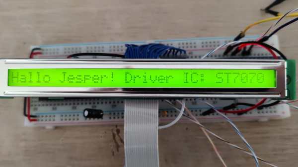
[Sudhir Chandra]’s detective story starts with a bunch of oddball LCDs, slim 1×32 character units rather than the more familiar 2×16 displays. Each bore the dreaded black COB blob on the back, as well as a handful of SMD components and not much else. Googling revealed no useful documentation, and the manufacturer wasn’t interested in fielding calls from a hobbyist. Reasoning that most manufacturers wouldn’t spin up a custom chip for every display, [Sudhir] assumed there was an ST7066, a common LCD driver chip, underneath the blob, especially given the arrangement of external components. But a jumper set was bodged together under this assumption didn’t get the display going.

Next up were more destructive methods, to decap the COB and see what kind of numbers might be on the chip. Sandpaper worked at first, but [Sudhir] eventually turned to the “Chips a la [Antoine]” method of decapping, which uses heat and brute force to get at the goods. This got down to the chip, but [Sudhir]’s microscope wasn’t up to the task of reading the die markings.

What eventually cracked the case was tracing out the voltages across the various external resistors and matching them up to other chips in the same family as the ST7066, plus the realization that the long, narrow epoxy blob probably covered a similarly shaped chip, which led to the culprit: an ST7070. This allowed [Sudhir] to build an adapter PCB for the displays, with plans for a custom Arduino library to talk to the displays.

This was a great piece of reverse engineering and a good detective story to boot. Hats off to [Sudhir] for sticking with it.