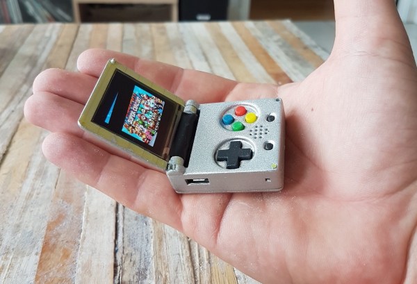
The world’s tiniest Game Boy Color, introduced at the 2016 Hackaday SuperConference, is a work of art. This microscopic game console inspired [c.invent] to create how own gaming handheld. His Keymu project on hackaday.io describes an open source, keychain-sized gaming handheld that its builder claims is really the world’s tiniest. How did he make it smaller? It’s a miniature Game Boy Advance SP, and it folds up in a handy clamshell case.
While he’s a Pi fan, [c.invent] felt the Pi Zero was too big and clunky for what he had in mind–a keychain-sized handheld. Only the Intel Edison was compact enough. He began with a custom PCB with a connector for the Edison’s fragile ribbon cable, then added an 1.5″ OLED display and an 11.7mm speaker, all powered by a 220 mAh lithium battery. [c.invent] also created inside a custom folding 3D-printed case that protects the Keymu’s electronics from keys and pocket lint.
Unlike the mini Game Boy Color, [c.invent] aims to create a fully fledged emulation console. The Edison incorporates a Linux distribution that allowing it to install emulators for GameBoy Color, GBA, NES, and SNES.
Nintendo has discontinued a Classic gaming console. It’s a pity, yes, but with the release of Nintendo’s new gaming console, they probably have bigger fish to fry. That doesn’t mean these discontinued Nintendo consoles will die a slow, miserable death locked away in a closet; at least one of them will live on with the heart of a Raspberry Pi.
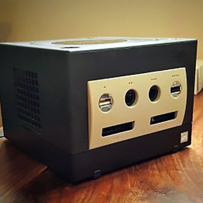
This is a project [Liam] has been working on since 2012, just after he got the first edition of the Raspberry Pi. While some people were figuring out how to stuff the Pi inside a Nintendo Entertainment System or a Super Nintendo Entertainment System, [Liam] decided to embed the Pi inside a console of a more recent vintage: the Nintendo GameCube.
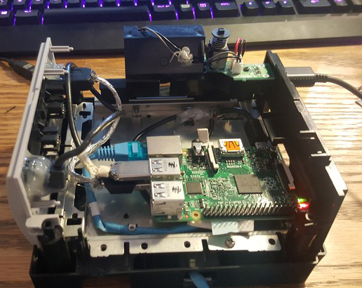
The first phase of this project was simply to get the Pi running inside the enclosure of the non-working GameCube he picked up. The power supply in this console was well designed, and after a quick perusal through some online documentation, [Liam] found a stable 5V with enough amps to power the Pi. After ripping out the internals of this console with the help of a quickly hacked together ‘Nintendo screwdriver’, [Liam] had a perfectly functional Pi enclosed in a Nintendo chassis.
Time marches on, and after a while, the Raspberry Pi 2 was released. By this time, retro emulation was hitting the big time, and [Liam] decided it was time for an upgrade. He disassembled this Nintendo console again, routed new wires and inputs to the original controller ports, and used a Dremel to route a few holes for the HDMI and SD card slot.
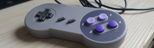
With the addition of a few SNES-inspired USB controllers, RetroPi, and a few ROMs, [Liam] has a wonderful console full of classic emulation goodness, packaged in an enclosure Nintendo isn’t making any more.
By far the most popular use for a Raspberry Pi is an emulation console. For an educational device, that’s fine – someone needs to teach kids how to plug a USB cable into a device and follow RetroPi tutorials on the Internet. These emulation consoles usually have one significant drawback: they’re ugly, with wires spilling everywhere. Instead of downloading a 3D printed Pi enclosure shaped like a Super Nintendo, [depthperfection] designed his own. It looks great, and doesn’t have a donglepocalypse hanging out the back.
The biggest factor in building an enclosure for a Pi Zero is how to add a few USB ports. There’s only one USB port on the Pi Zero, although if you’re exceptionally skilled, you can solder a hub onto the test points on the bottom of the board. This stackable USB hub solves the problem with the help of pogo pins for the power and USB pair. It’s only $17 USD, too.
With the USB and power sorted, [depthperfection] set out to design an enclosure. This was modeled in Fusion360, with proper vent holes, screw bosses, and cutouts for all the ports. It’s designed to be 3D printable, and with a little ABS smoothing, this enclosure looks great.
For software, [depthperfection] turned to Recallbox, a retrogaming platform that also doubles as a media player. It’s simpler than a RetroPi installation, but for playing Super Mario 3, you don’t really need many configuration options. This is a great project that just works and looks good doing it. The world — and the Raspberry Pi community — needs more projects like this, and we’re glad [depthperfection] sent this one in.
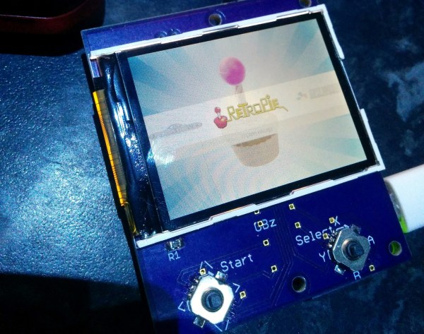
The most popular use for a Raspberry Pi, by far, is video game emulation. We see this in many, many forms from 3D printed Raspberry Pi cases resembling the original Nintendo Entertainment System to 3D printed Raspberry Pi cases resembling Super Nintendos. There’s a lot of variety out there for Raspberry Pi emulation, but [moosepr] is taking it to the next level. He’s building the smallest Pi emulation build we’ve ever seen.
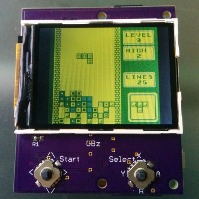
This build is based on the Pi Zero and a 2.2″ (0.56 dm) ili9341 TFT display. This display has a resolution of 240×320 pixels, which is close enough to the resolution of the systems the Pi Zero can emulate. The Pi Zero and display are attached to a beautiful purple breakout board (shared on OSH Park) along with a few 5-way nav switches, a charger for a Lipo battery, and a few other bits and bobs.
Right now, [moosepr] is experimenting with adding sound to his board. It’s easy enough to get sound out of a Pi Zero — it’s just PWM coming from a few pins — but audio also needs an amp, a speaker, and more space on the board. To solve this problem, [moose] found a few piezo transducers from musical greeting cards. These are designed to be thin and as loud as possible, and attaching these directly to the PWM pins providing audio might just work. This is a project to keep an eye on, if only to see if cheap piezos work for low-fi audio in retro emulators.
When I first got interested in computers, it was all but impossible for an individual to own a computer outright. Even a “small” machine cost a fortune not to mention requiring specialized power, cooling, and maintenance. Then there started to be some rumblings of home computers (like the Mark 8 we recently saw a replica of) and the Altair 8800 burst on the scene. By today’s standards, these are hardly computers. Even an 8-bit Arduino can outperform these old machines.
As much disparity as there is between an Altair 8800 and a modern personal computer, looking even further back is fascinating. The differences between the original computers from the 1940s and anything even remotely “modern” like an Altair or a PC are astounding. If you are interested in that kind of history, you should read a paper entitled “Electronic Computing Circuits of the ENIAC” by [Arthur W. Burks].
These mid-century designers used tubes and were blazing new ground. Part of what makes the ENIAC so different is that it had a different design principle than a modern computer. It was less a general purpose stored-program computer and more of a collection of logic circuits that could be configured to solve problems — sort of a giant vacuum tube FPGA, if you will. It used some internal representations that proved to be suboptimal which also makes it seem strange. The EDSAC — a later device — was closer to what we think of as a computer. Yet the ENIAC was a major step in the direction of a practical digital computer.
Cost and Size
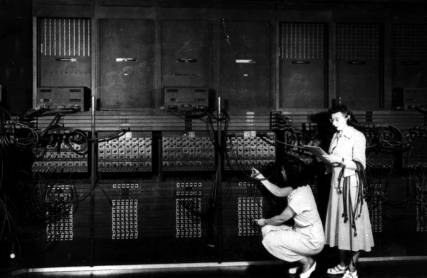
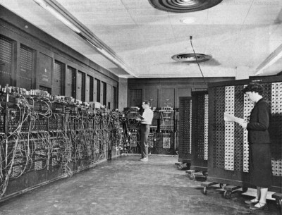
Programming the ENIAC in 1951 (±4 years) [Image Source: Public Domain]The size of ENIAC is hard to imagine. The device had about 18,000 tubes, 7,000 diodes, 70,000 resistors, 10,000 capacitors, and 6,000 switches. There were 5 million hand-soldered joints! ([Thomas Haigh] tells us that while this is widely reported, the real number was about 500,000.) Physically, it stood 10 feet tall, 3 feet deep, and 100 feet long. The tube filaments alone required 80 kW of power. Even the cooling system consumed 20 kW. In total, it took 150 kW to run the beast.
The cost of the machine was about $487,000. Almost a half-million dollars in 1946 is plenty. But that’s nearly seven million dollars in today’s money. What was worth that kind of expenditure? The military built firing tables for shell trajectories. From the [Burks] paper:
“A skilled computer with a desk machine can compute a 60-second trajectory in about twenty hours…”
Keep in mind that in 1946, a computer was a person. [Burks] goes on to say that a differential analyzer can do the same job in 15 minutes. ENIAC, on the other hand, could do it in 30 seconds and with a greater precision than the differential analyzer.
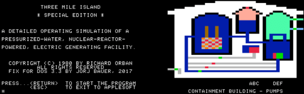
Emulators are a great way to reminisce about games and software from yesteryear. [Jorj Bauer] found himself doing just that back in 2002, when they decided to boot up Three Mile Island for the Apple II. It played well enough, but for some reason, crashed instantly if you happened to press the ‘7’ key. This was a problem — the game takes hours to play, and ‘7’ is the key for saving and restoring your progress. In 2002, [Jorj] was content to put up with this. But finally, enough was enough – [Jorj] set out to fix the bug in Three Mile Island once and for all.
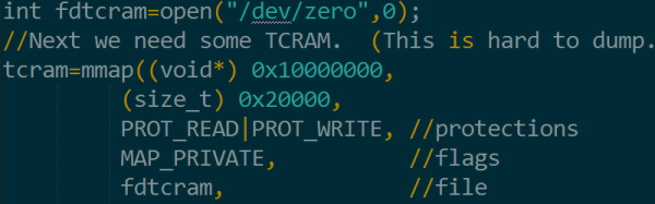
The project is written up in three parts — the history of how [Jorj] came to play Three Mile Island and learn about Apple IIs in the first place, the problem with the game, and finally the approach to finding a solution. After first discovering the problem, [Jorj] searched online to see if it was just a bad disk image causing the problem. But every copy they found was the same. There was nothing left for it to be but problem in the binary.
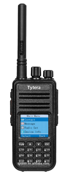
Right now, I’m at Shmoocon, and it’s living up to all expectations. That’s a tall order — last year, the breakout talk was from [Travis Goodspeed] on his efforts to reverse engineer the firmware for a cheap Chinese radio. Four people in the room for that talk last year bought the radio on Amazon, and now there’s a legitimate open source project dedicated to building firmware and tools to support this radio.
Now that [Travis] has a few compatriots working on firmware for this radio, he has the same challenges as any other team. The project needs unit tests, and this isn’t easy to do when all the code is locked up inside a radio. Instead of setting up an entire development platform based around a cheap radio, [Travis] came up with a toolchain that’s unlike anything I’ve ever seen. Instead of reverse engineering the firmware for this radio, he’s simply emulating the ARM firmware on the desktop. Development is quick and easy, and he has the live demos to prove it.
The heart of the Tytera radio in question is an STM32F405. This is a pretty common part, and thanks to [Travis]’ work last year, he has all the firmware that ships on this radio. This doesn’t mean he has access to all the radio’s capabilities, though; there’s a black box in the code somewhere that translates .wav files to radio packets and back again. Open sourcing this would usually mean reverse engineering, but [Travis] had a better idea.
Instead of reverse engineering the entire radio, [Travis] is using QEMU to emulate an ARM microcontroller on his desktop, run the relevant code, and completely ignore any actual reverse engineering. Since this radio is already jailbroken and the community has a pretty good idea of where all the functions and subroutines are in the firmware, the most difficult part of pulling this trick off is setting up QEMU.
As a proof of concept, [Travis] downloaded raw AMBE packets from the radio to his laptop. These were then sent through the emulated radio, producing raw audio that was then converted into a .wav file. Effectively, a black box in this radio was emulated, which means [Travis] doesn’t need to know how the black box works.
All the code for this weird emulation / unit test, as well as everything the community has released for this radio is available on the GitHub. A lot of work has gone into the jailbreaking, reverse engineering, and emulation efforts here, making this radio somewhat ironically one of the most open radios you can buy.


 Time marches on, and after a while, the Raspberry Pi 2 was released. By this time, retro emulation was hitting the big time, and [Liam] decided it was time for an upgrade. He disassembled this Nintendo console again, routed new wires and inputs to the original controller ports, and used a Dremel to route a few holes for the HDMI and SD card slot.
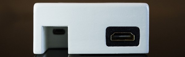


 This build is based on the Pi Zero and a 2.2″ (0.56 dm) ili9341 TFT display. This display has a resolution of 240×320 pixels, which is close enough to the resolution of the systems the Pi Zero can emulate. The Pi Zero and display are attached to a beautiful purple breakout board (