PCBs are exceptionally cheap now, and that means everyone gets to experiment with the careful application of copper traces on a fiberglass substrate. For his Hackaday Prize entry, [Carl] is putting coils on a PCB. What can you do with that? Build a motor, obviously. This isn’t any motor, though: it’s a linear motor. If you’ve ever wanted a maglev train on a PCB, this is the project for you.
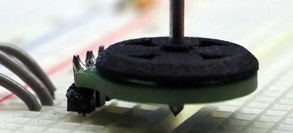
This project is a slight extension of [Carl]’s other PCB motor project, the aptly named PCB Motor. For this project, [Carl] whipped up a small, circular PCB with a few very small coils embedded inside. With the addition of a bearing, a few 3D printed parts, and a few magnets, [Carl] was able to create a brushless motor that’s also a PCB. Is it powerful enough to use in a quadcopter? Probably not quite yet.
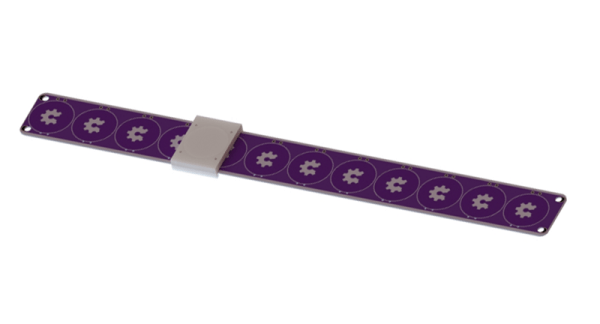
Like [Carl]’s earlier PCB motor, this linear PCB motor follows the same basic idea. The ‘track’, if you will, is simply a rectangular PCB loaded up with twelve coils, each of them using 5 mil space and trace, adding up to 140 turns. This is bigger than the coils used for the (circular) PCB motor, but that only means it can handle a bit more power.
As for the moving part of this motor, [Carl] is using a 3D printed slider with an N52 neodymium magnet embedded inside. All in all, it’s a simple device, but that’s not getting to the complexity of the drive circuit. We’re looking forward to the updates that will make this motor move, turning this into a great entry for The Hackaday Prize.