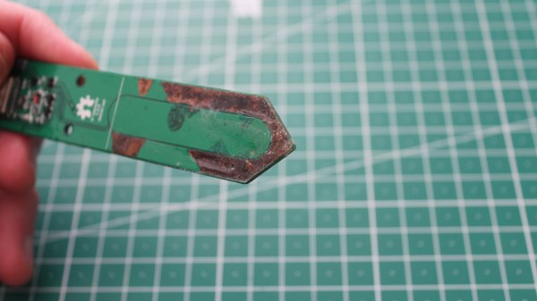
A soil moisture sensor with silkscreen chipped and copper corroded

Soil Moisture Sensor Coating Lessons Learned The Hard Way

Ever wanted to measure soil moisture? Common “soil moisture meter module arduino raspberry compatible free shipping” PCBs might deceive you with their ascetic looks. Today, [Raphael (@rbaron_)] is here to teach us (Twitter, unrolled) what it takes to build a soil-embedded sensor that can actually survive contact with a plant.

As the picture might hint, waterproofing is of paramount importance, and soldermask doesn’t quite cut it. Raphael describes his journey of figuring out approaches and coatings that would last, starting from simply using nail polish, and ending with the current option – a rotisserie-like device that rotates sensors as the coating applied to them dries, mitigating a certain kind of structural failure observed long-term. With plenty of illustrative pictures and even a video of the rotisserie device in action, you’ll quickly learn things that took time and effort for Raphael to figure out.

This isn’t the first time Raphael shares some design battlefield stories and lessons with us – he has taught us about overall capacitive moisture sensor principles, too! If that interests you, we’ve covered quite a few moisture sensor designs, from cheap but hardy two-nails designs to flip-dot-equipped ones, and some of us take the commercial designs and upgrade them!

We thank [Chaos] for sharing this with us!

Continue reading “Soil Moisture Sensor Coating Lessons Learned The Hard Way” →
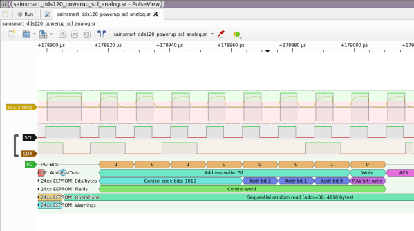
Screenshot of Pulseview showing capture and decode of some digital channels

Need A Logic Analyzer? Use Your Pico!

There’s a slew of hardware hacker problems that a logic analyzer is in a perfect position to solve. Whether you’re trying to understand why an SPI LCD screen doesn’t initialize, what’s up with your I2C bus, or determine the speed of an UART connection, you’ll really want to have a logic analyzer on hand. People have been using a Pi Pico as a logic analyzer in a pinch, and now [pico-coder] has shared a sigrok driver that adds proper support for a Pico to beloved tools like Pulseview.

The specs offered are impressive. Compared to the $10 “Saleae” clone analyzers we are so used to, this thing boasts 21 digital channels with up to 120 MHz capture speed, 3 ADC channels at up to 500 KHz, and hardware-based triggers. The GitHub repository linked above stores the driver files out-of-tree, but provides build instructions together with an easily flash-able uf2 firmware. It’s likely that you’ll soon see this driver in a stock Pulseview installation, however, given the submitter-friendly attitude we’ve witnessed on the sigrok mailing list. However, if you need a logic analyzer ASAP, you should follow the caringly offered quickstart guide.

We’ve covered Pulseview being used in combination with cheap accessible analyzers before — a must-watch if you need to get yourself up to speed on the value they provide to a hobbyist. If an oscilloscope is what you need and a smartphone is what you have, perhaps you’ll enjoy the Scoppy firmware for the Pico.

We thank [mip] for sharing this with us!

The teeny tiny MCU mentioned in the article, merely a blimp on a giant devboard

New Part Day: Smallest ARM MCU Uproots Competition, Needs Research

We’ve been contacted by [Cedric], telling us about the smallest ARM MCU he’s ever seen – Huada HC32L110. For those of us into miniature products, this Cortex-M0+ package packs a punch (PDF datasheet), with low-power, high capabilities and rich peripherals packed into an 1.6mm x 1.4mm piece of solderable silicon.

This is matchstick head scale computing, with way more power than we previously could access at such a scale, waiting to be wrangled. Compared to an 8-bit ATTiny20 also available in WLCSP package, this is a notable increase in specs, with a way more powerful CPU, 16 times as much RAM and 8-16 times the flash! Not to mention that it’s $1 a piece in QTY1, which is about what an ATTiny20 goes for. Being a 0.35mm pitch 16-pin BGA, your typical board house might not be quite happy with you, but once you get a board fabbed and delivered from a fab worth their salt, a bit of stenciling and reflow will get you to a devboard in no time.

Drawbacks? No English datasheet or Arduino port, and the 67-page PDF we found doesn’t have some things like register mappings. LILYGO promised that they will start selling the devboards soon, but we’re sure it wouldn’t be hard for us to develop our own. From there, we’d hope for an ESP8266-like effect – missing information pieced together, translated and made accessible, bit by bit.

When it comes to soldering such small packages, we highly recommend reflow. However, if you decide to go the magnet wire route, we wouldn’t dare object – just make sure to send us pictures. After all, seems like miniature microcontrollers like ATTiny20 are attractive enough of a proposition that people will pick the craziest route possible just to play with one. They say, the madness of the brave is the wisdom of life.

We thank [Cedric] for sharing this with us!

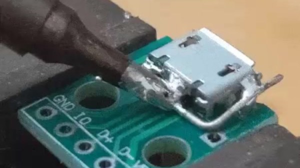
Soldering iron tip heating up a piece of wire wrapped around the metal parts of a MicroUSB socket, with melted solder heating up all the important parts.

Desoldering Without Hot Air: Piece Of Wire Edition

Quite a few hackers nowadays share their tips and tricks on Twitter – it’s easy to do so, and provided either an existing audience or a bit of effort to get one, you’ll get at least a few notifications telling you that people appreciated what you had to share. Today, we’re covering two desoldering hacks highlighted there that will be useful some day, exactly when you need them. Both of them use a piece of wire and, in a way, extend the reach of your soldering iron’s tip. Copper wire would work better because of superior thermal conductivity, but other types of solid core wire will work in a pinch.

First hack is brought to us by [Erin Rose] – desoldering a microUSB socket. You need to heat up the entire shield and the pins at the same time, which the wire acts as a thermal gateway for. As long as there are melted solder bridges from sections of the wire to all the copper-to-part connection points, it should be easy to pump enough heat into the solder joints for all of them to eventually melt and give in at once.

Second hack is brought to us by [arturo182]. A piece of thick wire acts, again, as a heat conductor to desolder a 0.5mm pitch TQFP-100 package IC. You have to bend the wire into a correct shape, so that it’s as close to the pins of the TQFP as possible. In this situation, the wire performs two functions: first, transferring the heat from the iron’s tip to different points along the wire, then, as a barrier that helps solder not escape too far away from the pins. Copious amounts of flux likely desired for this one!

Hopefully, this comes handy if you ever need to replace an all-SMD part ASAP but don’t have a hot air gun or a hotplate handy. After getting this concept down to an art, we are sure you won’t limit yourself to TQFP parts and MicroUSB sockets. We’ve talked about desoldering practices before as part of our newsletter, and using lots of melted solder for part removal is not a foreign concept to us, either.

Continue reading “Desoldering Without Hot Air: Piece Of Wire Edition” →

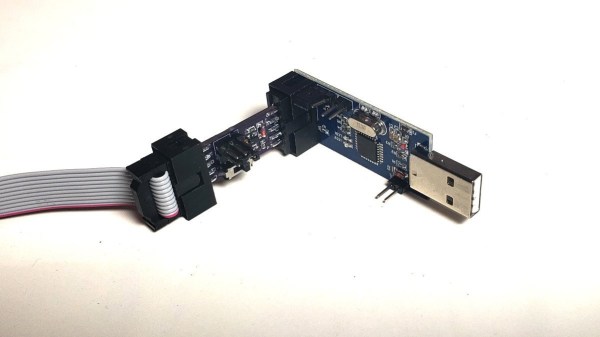
A HVTPI adapter plugged into a USBASP, with a an IDC10 cable plugged into it in turn

HVTPI Primer And Toolkit Equips You For BOM Substitutions

Novel programming interfaces for MCUs might catch us by surprise, but then we inevitably get up to speed with the changes required. Today’s bastion is HVTPI – a “12V reset” addition to the TPI we’ve just started getting used to, and [Sam Ettinger] has shared a simple circuit to teach us all about it, along with PCB files and detailed explanations of how it all works.

HVTPI is an add-on on top of TPI, for which, as Sam explains, you need to hold RST at 12V when TPI would have it be low logic level, and leave it at Vtarget otherwise. For that, he has designed a variety of interposer boards of various complexity and requirements; explaining the choices behind each one and clearing up any misunderstandings that might occur on your way. All of the board files (and the TPI write-up copy) are caringly shared with us in a git repository, too! As a result, if you have an USB-ASP or an Arduino available, now you also have everything to do HVTPI, thanks to Sam’s work and explanations.

We’ve been covering Sam’s exploits before, and can’t help but be grateful for the stop-and-explain detour along the way. HVTPI being used on very small ATTiny parts, we wonder if something new in the vein of his recent FPC board able to fit and function entirely within a Type-C cable end!

With chip shortages, investigating programming interfaces for small and obscure yet in-stock microcontrollers has been, quite literally, paying off, and if you got some projects that need a MCU but won’t consume a whole lot of resources, it could be time to give an ATTiny10 a go. What’s the worst that can happen – you make the smallest chiptunes ever?

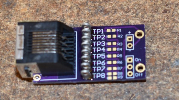
Receiver board of the Ethernet tester, with only probing pins, and no resistors populated

Ethernet Tester Needs No LEDs, Only Your Multimeter

Ethernet cable testers are dime a dozen, but none of them are as elegant and multimeter-friendly as this tester from our Hackaday.io regular, [Bharbour]. An Ethernet cable has 8 wires, and the 9 volts of easily available batteries come awfully close to that – which is why the board has a voltage divider! On the ‘sender’ end, you just plug this board onto the connector, powered by a 9 volt battery. On the “receiver” end, you take your multimeter out and measure the testpoints – TP7 should be at seven volts, TP3 at three volts, and so on.

As a result, you can easily check any of the individual wires, as opposed to many testers which only test pair-by-pair. This also helps you detect crossover and miswired cables – while firmly keeping you in the realm of real-life pin numbers! This tester is well thought-out when it comes to being easily reproducible – the PCB files are available in the “Files” section, and since the “receiver” and “sender” PCBs are identical, you only need to do a single “three PCBs” order from OSHPark in order to build your own!

Bharbour has a rich library of projects, and we encourage you to check them out! If you ever want to get yourself up to speed on Ethernet basics, we’ve talked about its entire history – and we’ve even explained PoE! After some intensive learning time, perhaps you can try your hand at crimping the shortest Ethernet cable ever.

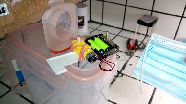
Mask DIY sanitization device on the left, mask used as an example on the right. The device is a Tupperware-like plastic container, on top, a small motor plus battery device with an alligator clip attached to the motor. Mask is inserted into the container through the opening on top, hooked to the motor, and the motor then spins the mask inside the container where hydrogen peroxide vapor is being misted.

Mask Sanitization That Anyone Can Build

We’ve seen a wide variety of mask sanitization solutions, and now, [spiritplumber] from [Robots Everywhere] brings us a frugal and ingenious design – one that you barely even need tools for. This project might look rough around the edges but looks were never a prerequisite, and as a hacker worth their salt will recognize – this is an answer to “how to design a mask disinfector that anyone can build”.

Local shortages of masks have been threatening communities here and there, doubly so if you need a specific kind of mask that might be out of stock. This design could apply to a whole lot of other things where sterilization is desired, too – improving upon concepts, after all, is our favourite pastime.

The design is simple – a battery-powered motor rotating a mask inside a vat of concentrated H2O2, turned into mist by a cheap ultrasonic misting gadget. As the “turntable” rotates a your PPE of choice, making sure that every crevice is graced with cleaning touch of peroxide, it also causes the H2O2 mist to circulate. Fulfilling most important requirements for a proper sanitization system that more complex devices have been struggling with, this approach has certainly earned its place under the sun.

[Robots Everywhere] have shared a small library of their DIY PPE resources with all of us, and that’s not all they work on – recently, we’ve seen their aeroponics project rejuvenating garlic.

Using hydrogen peroxide vapour for PPE sanitization is a well-tested approach by now, as we’ve seen it deployed back in 2020 on a larger scale as part of an FDA-approved design. And if you only have 3% peroxide at hand, might as well try concentrating it further!

Continue reading “Mask Sanitization That Anyone Can Build” →