Seth Molson Is Designing The Future, One Show At A Time

From the banks of levers and steam gauges of 1927’s Metropolis to the multicolored jewels that the crew would knowingly tap on in the original Star Trek, the entertainment industry has always struggled with producing imagery of advanced technology. Whether constrained by budget or imagination, portrayals usually go in one of two directions: they either rely too heavily on contemporary technology, or else they go so far in the opposite direction that it borders on comical.

Seth Molson

But it doesn’t always have to be that way. In fact, when technology is shown properly in film it often serves as inspiration for engineers. The portrayal of facial recognition and gesture control in Minority Report was so well done that it’s still referenced today, nearly 20 years after the film’s release. For all its faults, Star Trek is responsible for a number of “life imitating art” creations; such as early mobile phones bearing an unmistakable resemblance to the flip communicators issued to Starfleet personnel.

So when I saw the exceptional use of 3D printing in the Netflix reboot of Lost in Space, I felt it was something that needed to be pointed out. From the way the crew made use of printed parts to the printer’s control interface, everything felt very real. It took existing technology and pushed it forward in a way that was impressive while still being believable. It was the kind of portrayal of technology that modern tech-savvy audiences deserve.

It left such an impression that we decided to reach out to Seth Molson, the artist behind the user interfaces from Lost in Space, and try to gain a little insight from somebody who is fighting the good fight for technology in media. To learn how he creates his interfaces, the pitfalls he navigates, and how the expectations of the viewer have changed now that we all have a touch screen supercomputer in our pocket.

Continue reading “Seth Molson Is Designing The Future, One Show At A Time”

Creating A 3G Raspberry Pi Smartphone

It’s hard to believe, but the Raspberry Pi has now been around long enough that some of the earliest Pi projects could nearly be considered bonafide vintage hacks at this point. A perfect example are some of the DIY Raspberry Pi smartphone projects that sprung up a few years back. Few of them were terribly practical to begin with, but even if you ignore the performance issues and bulkiness, the bigger problem is they relied on software and cellular hardware that simply isn’t going to cut it today.

Which was exactly the problem [Dylan Radcliffe] ran into when he wanted to create his own Pi smartphone. There was prior art to use as a guide, but the ones he found were limited to 2G cellular networks which no longer exist in his corner of the globe. He’s now taken on the quest to develop his own 3G-capable Pi smartphone, and his early results are looking very promising.

Inside the phone, which he calls the rCrumbl, [Dylan] has crammed a considerable amount of hardware. A Raspberry Pi 3B+ with attached Adafruit touchscreen LCD is the star of the show, but there’s also a Pi camera module, battery charging circuit, and Adafruit FONA 3G modem (which also provides GPS). Powering the device is a 2500 mAh 3.7V battery, which reportedly delivers a respectable 8 to 12 hour runtime.

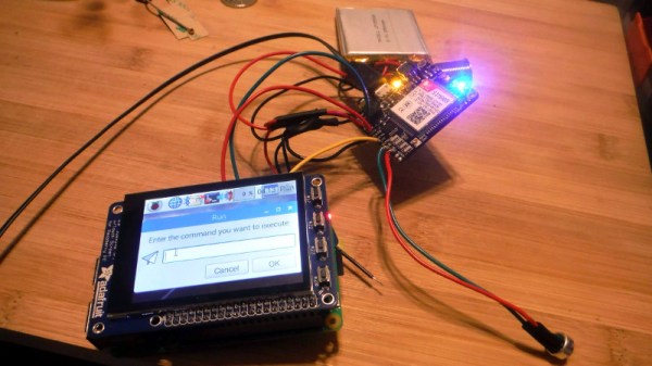
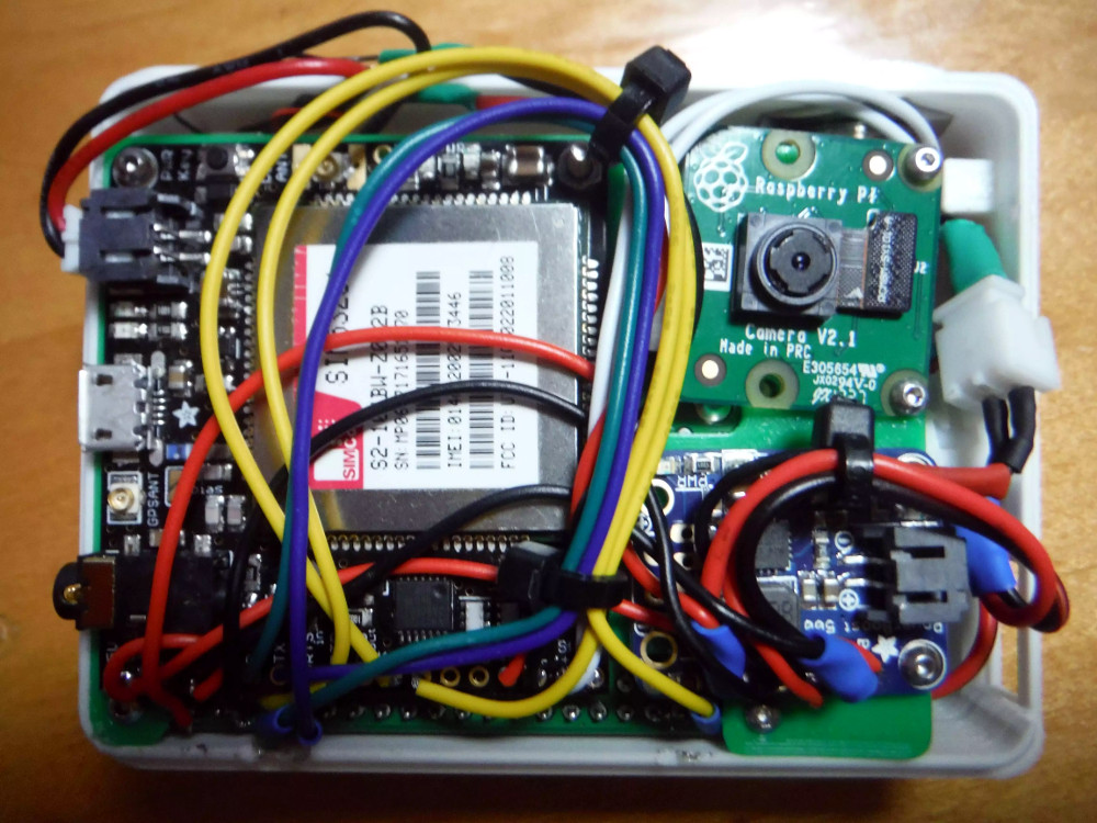
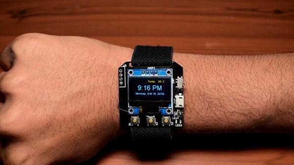
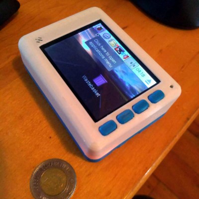
The case is 3D printed, and [Dylan] says it took a long time to nail down a design that would fit all of his hardware, keep things from shifting around, and still be reasonably slim. Obviously DIY phones like this are never going to be as slim as even the chunkiest of modern smartphones, but the rCrumbl looks fairly reasonable for a portable device. We especially like the row of physical buttons he’s included along the bottom of the screen, which should help with the device’s usability.

Speaking of usability, that’s where [Dylan] still has his work cut out for him. The existing software he’s found won’t work on 3G, so he’s going to have to come up with his own software stack to provide a proper phone interface. As it stands he’s made a call on the rCrumbl using command line tools, but while that might score you some extra geek points at the next hacker meetup, it’s not exactly going to fly for daily use. He mentions he would love to talk to any developers out there that would like to team up on the software side of the project.

We’ve covered one of the 2G Pi smartphones in the past, and of course the ZeroPhone is a very interesting project if you don’t mind the “dumb phone” interface. But if you’re looking for something that’s fairly close to commercial devices in terms of usability, you might just want to roll your own Android phone.

Easy Blinking LED Eyes For Halloween

There’s not much time left now. If you’re going to put something together to give the youngsters some night terrors in exchange for all that sweet candy, you better do it quick. This late to the game you might not have time to do anything too elaborate, but luckily we’ve come across a few quick Halloween hacks that can get you some pretty cool effects even if it’s only a few hours before the big night.

As a perfect example, these LED “blinking eyes” were created by [Will Moser]. Using nothing more exotic than some bare LEDs, an Arduino, and a cardboard box, these little gadgets can quickly and easily be deployed in your windows or bushes to produce an unsettling effect after the sun goes down. Thanks to the pseudorandom number generator in the Arduino code, the “eyes” even have a bit of variability to them, which helps sell the idea that your Halloween visitors are being watched by proper creatures of the night.

The hardware side of this project is very simple. [Will] takes a container such as a small cardboard box and cuts two holes in it to serve as the eyes. He notes that containers which are white or reflective on the inside work best. You’ll want to get a little artistic here and come up with a few different shaped sets of eyes, which is demonstrated in the video after the break. Inside each box goes a colored LED, wired back to the Arduino.

For the software, [Will] is using a floating analog pin as a source of random noise, and from there comes up with how often each LED will blink on and off, and for how long. Both the hardware and software sides of this project are perfect for beginners, so it might be a good way to get the Little Hackers involved in the festivities this year; if you’re the type of person who enjoys replicating small humans in addition to creeping them out.

LEDs seem to be the hacker’s decoration of choice come Halloween, from wearable LED eyes to remote controlled illuminated pumpkins.

Continue reading “Easy Blinking LED Eyes For Halloween”

Custom LED Signage From Household Items

We’ll admit it: sometimes we overthink things. We imagine some of you are the same way; there seems to be something in the hacker mentality that drives us to occasionally over-engineer ideas to the point of unrecognizability. There’s nothing inherently wrong with this, but sometimes it does keep us from seeing easier solutions.

For example, the very slick looking personalized LED sign (Google Translate) that [Clovis Fritzen] recently wrote in to share with us. If we were tasked with creating something like this there would certainly have been a 3D printer and likely a CNC involved before all was said and done, and a few days later we’d still be working out the bugs in our OpenSCAD code. But his approach is very different. Fantastically simple and constructed largely from household items, this is a good project to keep the Junior Hackers entertained on a rainy weekend.

The first step of the process is to draw out the characters you want onto a piece of cardboard, and then carefully cut it out. If you’re worried that you’re not particularly artistic, this step will go a bit better if you print out the design and tape the paper over the cardboard to serve as a template. Once you’ve got your design cut out, you glue or tape a piece of standard printer paper over it. This is the face of the display; it just needs to be lit from behind.

If you wanted to make a sign that was just a single color and didn’t have individually addressable elements, then it would be enough to illuminate the whole cutout with a single light source. But where’s the appeal in that? As [Clovis] shows, you can get much better results by constructing a segmented box, with one LED in each cell. By wiring each LED to a pin on an Arduino or other microcontroller, you’ll have control over the color and brightness of each section of the sign.

Of course, if you’re not big on the whole cardboard aesthetic, you could even recreate this design with the aforementioned CNC and 3D printer. [Clovis] shows how the basic concept works, and that it can be scaled pretty easily depending on the kind of materials you have access to.

Rebuilding An Amiga 500 PSU

One of the challenges of keeping a vintage computer up and running is the limited availability of spare parts. While not everything has hit dire levels of availability (not yet, anyway), it goes without saying that getting a replacement part for a 30+ year old computer is a bit harder than hitting up the local electronics store. So the ability to rebuild original hardware with modern components is an excellent skill to cultivate for anyone looking to keep these pieces of computing history alive in the 21st century.

This is in ample evidence over at [Inkoo Vintage Computing], where repairs and upgrades to vintage computers are performed with a nearly religious veneration. Case in point: this detailed blog post about rebuilding a dead Amiga 500 power supply. After receiving the machine as a donation, it was decided to attempt to diagnose and repair the PSU rather than replace it with a newly manufactured one; as much for the challenge as keeping the contemporary hardware in working order.

What was found upon opening the PSU probably won’t come as a huge surprise to the average Hackaday reader: bad electrolytic capacitors. But these things weren’t just bulged, a few had blown and splattered electrolyte all over the PCB. After removing the bad caps, the board was thoroughly inspected and cleaned with isopropyl alcohol.

[Inkoo Vintage Computing] explains that there’s some variations in capacitor values between different revisions of the Amiga PSU, so it’s best to match what your own hardware had rather than just trying to look it up online. These capacitors in particular were so old and badly damaged that even reading the values off of them was tricky, but in the end, matching parts were ordered and installed. A new fuse was put in, and upon powering up the recapped PSU, the voltages at the connector were checked to be within spec before being plugged into the Amiga itself.

As a test, the Amiga 500 was loaded up with some demos to really get the system load up. After an hour, the PSU’s transformer was up to 78°C and the capacitors topped out at 60°C. As these parts are rated for 100°C (up from 85°C for the original parts), everything seemed to be within tolerances and the PSU was deemed safe for extended use.

This sort of repair isn’t exactly rare with hardware this old, and we’ve seen similar work done on a vintage Apple power supply in the past. If you’re less concerned with historical accuracy, [Inkoo Vintage Computing] has also shown off adapting an ATX PSU for use with the Amiga.

A Multifunction ESP8266 Smartwatch

Most of the DIY smartwatch projects we feature here on Hackaday aren’t exactly what most people would consider practical daily-use devices. Clunky designs, short battery life, limited functions: they’re more a wearable display of geek cred than they are functional timepieces. Oddly enough, the same could be said of many of the “real” smartwatches on the market, so perhaps the DIY versions are closer to the state-of-the-art than we thought.

But this ESP8266 smartwatch created by [Shyam Ravi] is getting dangerously close to something you could unironically leave the house with. It’s still missing an enclosure that prevents you from receiving PCB acupuncture while wearing it, but beyond than that it has a more than respectable repertoire of functions. It even seems to be a fairly reasonable size (with the potential to be even smaller). All that with a total build cost of less than $20 USD, and we’re thinking this might be a project to keep an eye on.

Not content with a watch that simply tells the time, [Shyam] added in a weather function that pulls the current conditions for his corner of the globe from the Yahoo weather API and displays it above the time and date on the watch’s multi-color OLED display when the center button is pressed. Frankly, given the state of DIY watches, that would already have been impressive enough; but he didn’t stop there.

The left and right buttons control Internet-connected relays which [Shyam] uses to turn his lights and air conditioner on and off. When he presses the corresponding button, the watch will even display the status of the devices wherever his travels might take him.

A smattering of DIY watches pass by our careful gaze, though it’s been a while since we’ve seen an ESP8266 watch. More recently we’ve seen an Arduino watch, and some downright gorgeous analog creations.

Continue reading “A Multifunction ESP8266 Smartwatch”

Building A Proof Of Concept Hardware Implant

You’ve no doubt heard about the “hardware implants” which were supposedly found on some server motherboards, which has led to all sorts of hand-wringing online. There’s no end of debate about the capabilities of such devices, how large they would need to be, and quite frankly, if they even exist to begin with. We’re through the looking-glass now, and there’s understandably a mad rush to learn as much as possible about the threat these types of devices represent.

EEPROM (left) can be edited to enable SMBus access on this card (header to the right)

[Nicolas Oberli] of Kudelski Security wanted to do more than idly speculate, so he decided to come up with a model of how an implanted hardware espionage device could interact with the host system. He was able to do this with off the shelf hardware, meaning anyone who’s so inclined can recreate this “Hardware Implant Playset” in their own home lab for experimentation. Obviously this is not meant to portray a practical attack in terms of the hardware itself, but gives some valuable insight into how such a device might function.

One of the most obvious attack vectors for hardware implants is what’s known as the Baseboard Management Controller (BMC). This is a chip used on modern motherboards to allow for remote control and monitoring of the system’s hardware, and promises to be a ripe target for attackers. There are a few sideband channels which can be used by the BMC chip to talk to other chips. To keep things simple [Nicolas] focused on the older I2C-derived SMBus (rather than the newer and more complex NC-SI), demonstrating what can be done once you have control of that bus.

Only problem was, he didn’t have a motherboard with a BMC to experiment with. After a little research, the answer came in the form of the Intel EXPI9301CTBLK network card, which features the 82574L SMBus chip. This allows for experimenting with a subset of SMBus functionality on any machine with a PCI-E slot. Even better, the card has an SMBus header on the top to plug into. [Nicolas] describes in detail how he enabled the SMBus interface by modifying the card’s EEPROM, which then allowed him to detect it with his HydraBus.

With the hardware setup, the rest of the write-up focuses on what you can do with direct control of SMBus on the network card. [Nicolas] demonstrates not only creating and sending Ethernet packets, but also intercepting an incoming packet. In both cases, a running instance of tcpdump on the host computer fails to see the packets even exist.

He goes on to explain that since SMBus is very similar to I2C and only requires four wires, the techniques shown could easily be moved from the Hydrabus dev board used in the demo, to a small microcontroller like the ATtiny85. But you would still need to find a way to add that microcontroller directly onto the network card without it being obvious to the casual observer.

Our previous coverage of suspected hardware implants sparked considerable discussion, and it looks like no matter what side of the fence you’re on, the debate isn’t going away anytime soon.