Don’t Look Now, But Your Necklace Is Listening

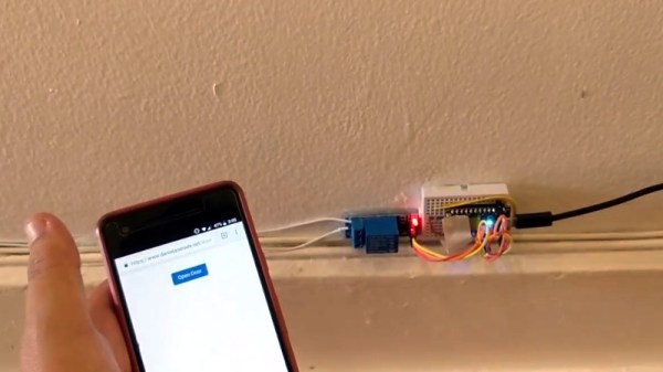
There was a time when the average person was worried about the government or big corporations listening in on their every word. It was a quaint era, full of whimsy and superstition. Today, a good deal of us are paying for the privilege to have constantly listening microphones in multiple rooms of our house, largely so we can avoid having to use our hands to turn the lights on and off. Amazing what a couple years and a strong advertising push can do.

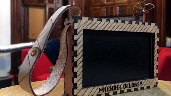
So if we’re going to be funneling everything we say to one or more of our corporate overlords anyway, why not make it fun? For example, check out this speech-to-image necklace developed by [Stephanie Nemeth]. As you speak, the necklace listens in and finds (usually) relevant images to display. Conceptually this could be used as an assistive communication technology, but we’re cool with it being a meme display device for now.

Hardware wise, the necklace is just a Raspberry Pi 3, a USB microphone, and a HyperPixel 4.0 touch screen. The Pi Zero would arguably be the better choice for hanging around your neck, but [Stephanie] notes that there’s some compatibility issues with Node.js on the Zero’s ARM6 processor. She details a workaround, but says there’s no guarantee it will work with her code.

The JavaScript software records audio from the microphone with SoX, and then runs that through the Google Cloud Speech-to-Text service to figure out what the wearer is saying. Finally it does a Google image search on the captured words using the custom search JSON API to find pictures to show on the display. There’s a user-supplied list of words to ignore so it doesn’t try looking up images for function words (such as “and” or “however”), though presumably it can also be used to blacklist certain imagery you might not want popping up on your chest in mixed company.

We’d be interested in seeing somebody implement this software on a Raspberry Pi powered digital frame to display artwork that changes based on what the people in the room are talking about. Like in Antitrust, but without Tim Robbins offing anyone.

Photon Door Lock Swaps Keys For A POST Request

At this point we’re all well aware of the fact that there is some inherent danger involved when bringing “things” onto the Internet. Nobody wants to come home to a smoldering pile of ruble because their Internet connected toaster oven decided to get stuck on “Hades.” But even with the risks, occasionally we see projects that prove at least some intrepid hackers are managing to navigate the Internet of Things to solve real-world problems.

[Daniel Andrade] writes in to tell us about the Internet controlled entry system he’s setup at his new apartment, and while we imagine it’s not for everyone, we can’t deny it seems like it has improved his quality of life. Rather than giving all of his friends a copy of his key, he’s setup a system where anyone who has the appropriate link can “buzz” themselves in through the building’s existing intercom system.

Thanks to the old-school intercom setup, the hardware for this project is simple in the extreme. All [Daniel] needed was a relay to close the circuit on the door buzzer, and a way to fire it off. For his controller he chose the Photon from Particle, which is perhaps a bit overkill, but we all tend to work with what we’re personally comfortable with.

Most of the work went into the software, as [Daniel] ended up coming with two distinct ways to control the door lock over the Internet. The first method uses Blynk, which allows you to create slick visual interfaces for mobile devices. His second version is controlled with a POST request to a specific URL, which he likes because it gives him more flexibility as to how he can interact with the lock. Currently he has a simple web page setup that lets friends and family open the door by just clicking a button.

We’ve seen a similar setup using the Photon to open a garage door, and plenty of people have taken to using Blynk to control their home automation setups. All the tools are available for you to roll your own IoT gadgets, you just need to figure out what to do with the things…

ESP8266 Powered Tank With Voice Control

The high availability of (relatively) low cost modular components has made building hardware easier than ever. Depending on what you want to do, the hardware side of a project might be the hacker equivalent of building with LEGO. In fact, we wouldn’t be surprised if it literally involved building with LEGO. In any event, easy and quick hardware builds leave more time for developing creative software to run the show. The end result is that we’re starting to see very complex systems broken down into easy-to-replicate DIY builds that would have been nearly impossible just a few years ago.

[igorfonseca83] writes in to share with us his modular tank platform that uses the ESP8266 and a handful of software hacks to allow for voice control from the user’s mobile device. Presented as a step-by-step guide on Hackaday.io, this project is perfect for getting started in Internet-controlled robotics. Whether you just want to experiment with Google Assistant integration or use this as a blank slate to bootstrap a remotely controlled rover, this project has a lot to offer.

The chassis itself is a commercially available kit, and [igorfonseca83] uses a L298N dual channel H-bridge module to control its two geared motors. A Wemos D1 serves as the brains of the operation, and three 18650 3.7V batteries provide the juice to keep everything running. There’s plenty of expansion capability to add sensors and other gear, but for this project getting it rolling was the only concern.

Software wise, there are a number of pieces that work together to provide the Google Assistant control demonstrated in the video after the break. It starts by interfacing the ESP8266 board Adafruit.IO, which connects to IFTTT, and then finally Google Assistant. By setting up a few two variable phrases in IFTTT that get triggered by voice commands in Google Assistant, you can push commands back down to the ESP8266 through Adafruit.IO. It’s a somewhat convoluted setup, admittedly, but the fact that involves very little programming makes it an interesting solution for anyone who doesn’t want to get bogged down with all the minutiae of developing your own Internet control stack.

[igorfonseca83] is no stranger to building remotely controlled rovers. Last year we covered another of his creations which was commanded through a web browser and carried an Android phone to stream video of its adventures.

Continue reading “ESP8266 Powered Tank With Voice Control”

Transistor Logic Clock Gets Stacked Up

A couple years back we covered a very impressive transistor logic clock which was laid out so an observer could watch all of the counters doing their thing, complete with gratuitous blinkenlights. It had 777 transistors on 41 perfboards, and exactly zero crystals: the clock signal was extracted from the mains frequency of 50 Hz. It was obviously a labor of love and certainly looked impressive, but it wasn’t exactly the most practical timepiece we’d ever seen.

Creator [B Brett] recently wrote in to share news that the second version of his transistor logic clock has been completed, and we can confidently say it’s a triumph. He’s dropped the 41 perfboards in favor of 9 professionally fabricated PCBs, which this time around are stacked vertically to make it a bit more desktop friendly. The end goal of a transistor logic clock that you can take apart to study is the same, but this “MkII” as he calls it is a far more refined version of the concept.

In addition to using fewer boards, the new MkII design cuts the logic down to only 283 transistors. This is thanks in part to the fact that he allowed himself the luxury of including an oscillator this time. The clock uses a standard watch crystal at 32.768 KHz, the output of which is converted into a square wave through a Schmitt trigger. This is then fed into a divider higher up the stack which uses flip flops to produce 1Hz and 2Hz signals for use throughout the rest of the clock.

In addition to the original version of this project, we’ve also seen a beautiful single-board wall mounted version, and even a “dead bug” style one built from scraps.

Continue reading “Transistor Logic Clock Gets Stacked Up”

ZPB30A1 Electronic Load Gets An Open Firmware

Importing cheap equipment and test gear is something of a mixed blessing. It allows you to outfit your lab without emptying your bank account, but on the other hand there’s usually a reason it’s cheap. Of course, the retail price of a piece of hardware shouldn’t be the metric by which we measure its quality, but there’s got to be a few corners cut someplace when they are selling this stuff for a fraction of what the name brands are charging.

A perfect example is the ZHIYU ZPB30A1 electronic load, available from various online importers for about $30 USD. While the price is right for an adjustable load that can handle up to 110 W, it’s got some pretty glaring shortcomings. In an effort to address at least some of those issues, [Luca Zimmermann] has been working on an open source replacement firmware for the load’s STM8S microcontroller.

[Luca] quickly discovered that the device’s STM8S005K6 chip is write protected, so unfortunately you can’t just flash a new firmware to it. If you want to unlock additional features, you need to perform a brain transplant. Luckily these chips are quite cheap, and you can probably add a couple of them to your cart when you order he ZPB30A1.

With the new GPLv3 licensed firmware installed, the device gains constant power and resistances modes (stock firmware can only do constant current), serial logging, and support for adjusting the value of the shunt resistor. There’s even a basic menu system to shuffle through the new modes. There’s still a couple features that haven’t been implemented, such as automatic shutdown, but it’s already a considerable upgrade from the stock software. Now we just need some details on the slick custom enclosure that [Luca] has put his upgraded ZPB30A1 into.

If this looks too easy, you can always go the DIY Arduino route for your load testing needs, or build a monster than can sink up to 1 kW.

[Thanks to Benik3 for the tip.]

3D Printed RC Jet Boat Gets Up To Speed

In one of those weird twists of fate, there’s currently a very high chance that anyone who owns a 3D printer has made a boat with it. In fact, they’ve probably printed several of them, so many that they might even have a shelf filled with little boats in different colors and sizes. That’s because it’s a popular benchmark to make sure the printer is well calibrated. But if you’re going to spend hours printing out a boat, why not print one that’s got some punch?

This 3D printable jet boat designed by [Jotham B] probably isn’t a great print to check your desktop machine’s calibration on, in fact you’re going to want to make sure you’ve got everything dialed in before taking on this challenge. If the classic “Benchy” is the beginners boat, then this is certainly for the 3D printing veterans. But if you’ve got the skills to pull it off, and some RC gear laying around to outfit it with, this could be a great project to end your summer on.

Unless you’ve got an exceptionally tall printer, the 460mm long hull will need to be printed in several pieces and then grafted back together. You could potentially use glue, but something a bit more robust like welding the parts together with a soldering iron is a better bet to make sure your printed boat doesn’t do its best Titanic reenactment out on the lake.

[Jotham] recommends printing the impeller at 0.15mm layer height, as you’ll want all the detail you can muster to provide a smooth surface. You’ll also need to use supports, so expect to spend a fair bit of time cleaning it up post-print. The rest of the model can be printed at 0.3mm, which is going to save a lot of time on the hull. All told, it will take about half a roll of filament to print all the parts for the boat (assuming no mistakes), which puts the pre-electronics cost at around $10 USD.

Speaking of electronics, you’ll need a RC receiver, a servo for steering, an electronic speed controller (ESC), and a suitable motor. [Jotham] used a 3674 brushless motor with a 120A water-cooled ESC, but notes that the setup is way overpowered. In the video after the break you can see the boat spends as much time airborne as it does in the water, which might look cool, but isn’t exactly efficient.

If you want to round out your 3D PLA fleet, we’ve also seen a printed FPV lifeboat as well as a hydrofoil that “flies” through the water.

[Thanks to Aidan for the tip.]

Continue reading “3D Printed RC Jet Boat Gets Up To Speed”

A Custom Built FPV Monitor To Keep The Fans Happy

If you’re going to be flying around a FPV-capable aircraft, be it a quadcopter or a fixed-wing plane, you shouldn’t be surprised if bystanders want to take a turn wearing your googles. Of course we hope that you’re good enough flying line of sight that you don’t need to be wearing the googles to stay airborne, but it does make it harder to pull off the sort of tricks and maneuvers that your audience wants to see. So if you want to put on a good show, the audience really needs their own display.

Unfortunately, as avid FPV flier [Michael Delaney] discovered, even the “cheap” ones will run you at least $100 USD. So he did what any self-respecting hacker would do, he set out to build his own. Using a collection of off the shelf components he was able to build a very impressive monitor that lets the viewer see through the eyes of his quadcopter at less than half the cost of commercially available offerings. Though even if he hadn’t manged to beat the cost of a turn-key monitor, we think it would have been more than worth it for this piece of highly customized gear.

At the heart of the monitor is a Boscam RX5808 5.8 GHz receiver, which is controlled by an Arduino Pro Mini. The video output from the receiver is sent to a 4.2″ TFT screen intended for the Raspberry Pi, and on the backside of the laser-cut wooden enclosure there’s a 128 x 64 I2C OLED to display the currently selected channel and diagnostic information.

An especially nice touch for this project is the custom PCB used to tie all the components together. [Michael] could have taken the easy route and sent the design out for fabrication, but instead went with the traditional method of etching his own board in acid. Though he did modernize the process a bit by using a laser and pre-sensitized copper clad board, a method that seems to be gaining in popularity as laser engravers become a more common component of the hacker’s arsenal.

We’ve previously covered using the RX5808 and Arduino combo to create a spectrum analyzer, in case you want to do more than just watch your friends do powerloops.