Waveform Generator Teardown Is Nearly Empty

We always enjoy [Kerry Wong]’s insightful teardowns, and recently, he opened up a UTG1042X arbitrary waveform generator. Getting inside was a bit of a challenge since there were no visible screws. Turns out, they were under some stickers. We always dislike that because it is very difficult to get the unit to go back together.

Once open, the case reveals it is almost completely empty. The back panel has a power supply, and the front panel has all the working circuitry. The box seems to be for holding the foot and preventing the device from getting lost on your bench.

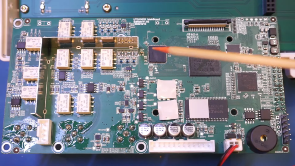
The power supply is unremarkable. There are a few odd output voltages. The main board is a bit more interesting, especially after removing the heat sink. There are two channels, but the board isn’t laid out, with a lot of segregation between the two channels. That makes sense with the output sections clustered together and the digital section with the CPU, FPGA, and the DAC in close proximity.

The other side of the board connects to a very simple display board. It would be interesting to compare this to a circa-1980s AWG, which would have been far more complicated.

Making a waveform generator with a microprocessor and a DAC isn’t hard. The hard part is the output stages and maximizing the operating speed.

Continue reading “Waveform Generator Teardown Is Nearly Empty”

HDMI DDC Keypad Controls Monitor From Rack

Sometime last year, [Jon Petter Skagmo] bought a Dell U3421WE monitor. It’s really quite cool, with a KVM switch and picture-by-picture support for two inputs at the same time. The only downside is that control is limited to a tiny joystick hiding behind the bezel. It’s such a pain to use that [Jon] doesn’t even use all of the features available.

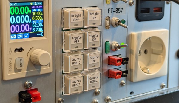
[Jon] tried ddcutil, but ultimately it didn’t work out. Enter the rack-mounted custom controller keyboard, a solution which gives [Jon] single keypress control of adjusting the brightness up and down, toggling picture-by-picture mode, changing source, and more.

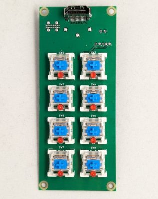
How does it work? It uses the display data channel (DDC), which is an I²C bus on the monitor’s HDMI connector. More specifically, it has a PIC18 microcontroller sending those commands via eight Cherry MX-style blues.

Check this out — [Jon] isn’t even wasting one of the four monitor inputs because this build uses an HDMI through port. The finished build looks exquisite and fits right into the rack with its CNC-routed aluminium front panel. Be sure to check it out in action after the break.

Ever wonder how given keyboard registers the key you’re pressing? Here’s a brief history of keyboard encoding.

Continue reading “HDMI DDC Keypad Controls Monitor From Rack”

Retro Hackintosh Made From Retro Parts

Apple as a company, has staked most of its future around being a “walled garden” where it controls everything from the hardware up through the user experience. In some ways this is good for users; the hardware is generally high quality and vetted by the company creating the software, making for a very uniform experience. This won’t stop some people from trying to get Apple’s operating systems and other software running on unapproved hardware though. These “Hackintosh” computers were much more common in the Intel era but this replica goes even further back to the Macintosh era.

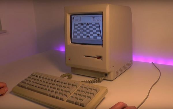
Originally [Kevin] had ordered an authentic Macintosh with the intent of getting it working again, but a broken floppy disk drive and lack of replacement parts turned this project into a different beast. He used the Mac instead as a model for a new 3D-printed case, spending a ton of time sanding, filling, and finishing it to get it to look nearly indistinguishable from the original. The hardware going in this replica is an old Linux-based thin client machine running the Mini vMac operating system, with a modified floppy drive the computer uses to boot. A hidden SD card slot helps interface with modern computers. The display is a modern LCD, though a sheet of acrylic glued to the front panel replicates a bit of the CRT curve.

Click through to read on!

Continue reading “Retro Hackintosh Made From Retro Parts”

High-Voltage Fun With An Inexpensive Power Supply

It used to be that nearly every home had at least one decent high-voltage power supply. Of course, it was dedicated to accelerating electrons and slamming them into phosphors so we could bathe ourselves in X-rays (not really) while watching Howdy Doody. These days the trusty tube has been replaced with LEDs and liquid crystals, which is a shame because there’s so much fun to be had with tens of thousands of volts at your disposal.

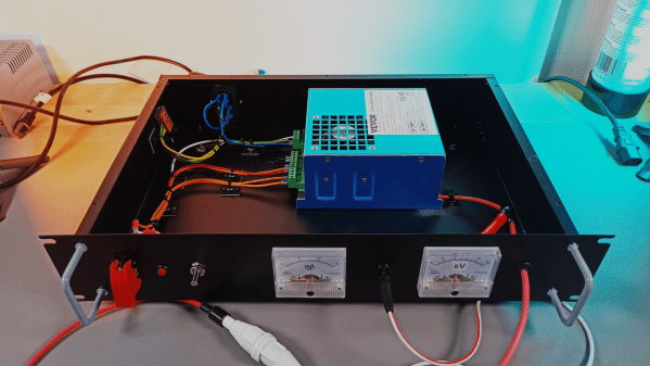
That’s the impetus behind this inexpensive high-voltage power supply by [Sebastian] over at Baltic Labs. The heavy lifting for this build is done by a commercially available power supply for a 50-watt CO2 laser tube, manufactured — or at least branded — by VEVOR, a company that seems intent on becoming the “Harbor Freight of everything.” It’s a bold choice given the brand’s somewhat questionable reputation for quality, but the build quality on the supply seems decent, at least from the outside. [Sebastian] mounted the supply inside a rack-mount case, as one does, and provided some basic controls, including the obligatory scary-looking toggle switch with safety cover. A pair of ammeters show current and voltage, the latter with the help of a high-voltage resistor rated at 1 gigaohm (!). The high-voltage feedthrough on the front panel is a little dodgy — a simple rubber grommet — but along with the insulation on the high-voltage output lead, it seems to be enough.

The power supply’s 30 kV output is plenty for [Sebastian]’s current needs, which from the video below appear to mainly include spark gap experiments. He does mention that 50 kV commercial supplies are available too, but it would be tough to do that for the $150 or so he spent on this one. There are other ways to go, of course — [Niklas] over at Advanced Tinkering recently shared his design for a more scratch-built high-voltage supply that’s pretty cool too. Whatever you do, though, be careful; we’ve been bitten by a 50 kV flyback supply before and it’s no joke.

Continue reading “High-Voltage Fun With An Inexpensive Power Supply”

Arctic Adventures With A Data General Nova II — The Equipment

As I walked into the huge high bay that was to be my part-time office for the next couple of years, I was greeted by all manner of abandoned equipment haphazardly scattered around the room. As I later learned, this place was a graveyard for old research projects, cast aside to be later gutted for parts or forgotten entirely. This was my first day on the job as a co-op student at the Georgia Tech Engineering Experiment Station (EES, since renamed to GTRI). The engineer who gave me the orientation tour that day pointed to a dusty electronic rack in one corner of the room. Steve said my job would be to bring that old minicomputer back to life. Once running, I would operate it as directed by the radar researchers and scientists in our group. Thus began a journey that resulted in an Arctic adventure two years later.

The Equipment

The computer in question was a Data General (DG) mini computer. DG was founded by former Digital Equipment Corporation (DEC) employees in the 1960s. They introduced the 16-bit Nova computer in 1969 to compete with DEC’s PDP-8. I was gawking at a fully-equipped Nova 2 system which had been introduced in 1975. This machine and its accessories occupied two full racks, with an adjacent printer and a table with a terminal and pen plotter. There was little to no documentation. Just to turn it on, I had to pester engineers until I found one who could teach me the necessary front-panel switch incantation to boot it up. Continue reading “Arctic Adventures With A Data General Nova II — The Equipment”

How To Build Your Own 16-Bit System-on-Spreadsheet

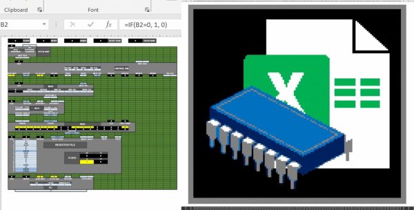
Back in the hazy days of the  early home computers, many of us would rejoice at running our first BASIC applications, some of us even built our own 8-bit system from a handful of ICs and felt elated the moment the connected LEDs, screen or other output device would show signs of life. It is this kind of excitement that [Inkbox] has managed to bring to the bane of every office worker: spreadsheet programs like Excel. How, you may ask? Why, by implementing a completely functional 16-bit system with 16 general purpose registers, 128 kB of RAM and a 128×128 pixel color display, all inside an Excel spreadsheet, making it conceivably the world’s first System-on-Spreadsheet (SoS).

Perhaps the most tantalizing aspect of this approach is that it provides a very good visual way to indicate what is happening inside the system using color codes and clearly segregated and marked functional elements. Not only can it be programmed manually, but [Inkbox] also created an assembler for the CPU’s ISA – called Excel-ASM16 – all of which is available from the ExcelCPU GitHub project page. The ASM is assembled into a ROM.xlsx file that can then be run by the CPU.xlsx file by triggering the Read ROM button. After this you are confronted with the realization that although it all works, it’s also incredibly slow, at about 2-3 Hz.

Still, with all the elegance of an IMSAI 8080 front panel, we cannot help but give full points for this achievement. Plus it gives many of us something to do during those exceedingly dull meetings where only serious applications like office suites are allowed.

Continue reading “How To Build Your Own 16-Bit System-on-Spreadsheet”

The scope, with new knobs and stickers on it, front panel renovated

Explosion-Scarred Scope Gets Plastic Surgery Hackerspace Style

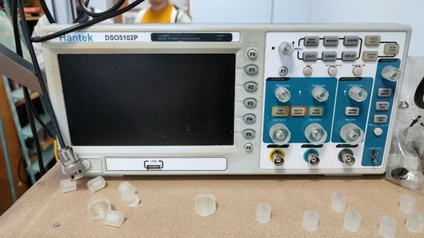
Some equipment comes with a backstory so impressive, you can’t help but treat it with reverence. For instance, this Hantek scope’s front panel and knobs have melted when a battery pack went up in flames right next to it. Then, it got donated to the CADR hackerspace, who have in turn given us a scope front panel refurbishing master class (translated, original), demonstrating just how well a typical hackerspace is prepared for performing plastic surgery like this.

All of the tools they used are commonplace hackerspace stuff, and if you ever wanted to learn about a workflow for repairs like these, their wiki post is a model example, described from start to end. They show how they could use a lasercutter to iterate through figuring out mechanical dimensions of the labels, cutting the silhouette out of cardboard as they tweaked the offsets. Then, they designed and printed out the new front panel stickers, putting them through a generic laminator to make them last. An FDM printer helped with encoder and button knob test fits, with the final version knobs made using a resin printer.

Everything is open-source – FreeCAD knob designs, SVG stickers, and their CorelDraw sources are linked in the post. With the open-source nature, there’s plenty of room to improvement – for instance, you can easily put these SVGs through KiCad and then adorn your scope with panels made out of PCBs! With this visual overhaul, the Hantek DSO5102P in question has gained a whole lot more character. It’s a comprehensive build, and it’s just one of the many ways you can compensate for a damaged or missing shell – check out our comprehensive DIY shell guide to learn more, and when you get to designing the front panel, we’ve highlighted a few lessons on that too.