 If you look up Bing Crosby in Wikipedia, the first thing you’ll notice is his real name was Harry. The second thing you’ll read, though, is that he is considered the first “multimedia star.” In 1948, half of the recorded music played on the air was by Bing Crosby. He also was a major motion picture star and a top-selling recording artist. However, while you might remember Bing for his songs like White Christmas, or for his orange juice commercials, or for accusations of poor treatment from his children, you probably don’t associate him with the use of magnetic tape.
In a way, Bing might have been akin to the Steve Jobs of the day. He didn’t power the technology for tape recording. But he did see the value of it, invested in it, and brought it to the market. Turns out Bing was quite the businessman. Want to know why he did all those Minute Maid commercials? He was a large shareholder in the company and was the west coast distributor for their products. He also owned part of the Pittsburgh Pirate baseball team and other businesses.
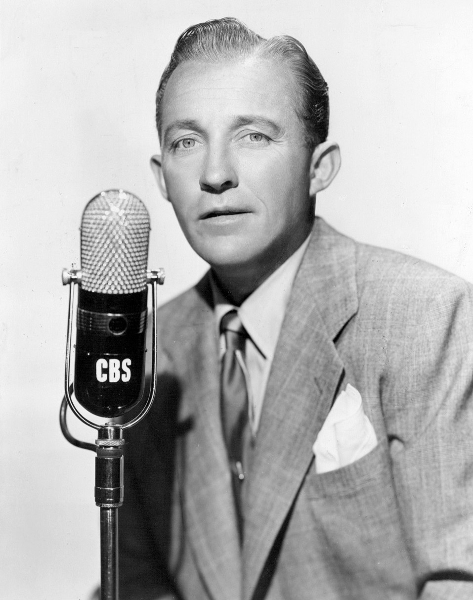
So how did Bing become instrumental in introducing magnetic tape recording? Because he was tired of doing live shows. You see, in 1936, Crosby became the host of a radio variety show, The Kraft Music Hall. This very popular program was live. That means you have to show up on time. If you go off on a tangent, you’ll run out of time. And if you make a mistake, there is no editing. Oh and one other thing. You have to do a nationwide live show twice: once for the east coast and another for the west. This was cutting into Bing’s “family time” which, as far as we can ascertain was a code phrase for golf.
Continue reading “Recorded Programming — Thanks To Bing Crosby”