This excellent content from the Hackaday writing crew highlights recurring topics and popular series like Linux-Fu, 3D-Printering, Hackaday Links, This Week in Security, Inputs of Interest, Profiles in Science, Retrotechtacular, Ask Hackaday, Teardowns, Reviews, and many more.
CERN is having a hackathon. It’s in October, yes, but the registration is closing on the 15th of June. They’ve been doing this every year, and the projects that come out of this hackathon are as diverse as infrastructure-less navigation, cosmic ray detectors, and inflatable refrigerators.
Have one of those solder fume extractors? Here’s an obvious improvement. [polyglot] put a strip of LEDs around the frame of his solder fume extractor to put a little more light on the subject.
A few months ago, [Bunnie] started work on a book. It was the Essential Guide to Electronics in Shenzhen. It’s made for hardware hackers to figure out how to buy stuff in Shenzhen, using a neat point-and-understand interface. Those books are now being shipped to people around the globe. I got one, and here’s the mini-review: it’s awesome. Is it a complete travel guide? No, but if you dropped me off at Hong Kong International, I could probably 1) Make it to Shenzhen 2) Buy random LEDs 3) Find a hotel 4) Get a beer 5) Not die. Pics below.
You’re hackers, and that means you’re the people who build stuff for all those ‘makers’ out there. Don’t have an MBA? No problem, [Dave Jones] has your back. He re-did his Economics of Selling Hardware video from several years ago. It’s 25 minutes long, and gives you enough information so you’re not a complete idiot at the business end of design.
If you’re into R/C, you know about Flite Test. They’re the folks that make crazy, crazy model planes out of Dollar Tree foam board, and have gotten hundreds of people into the hobby. Flite Test is having their own con, Flight Fest, in a little over a month. It’s in Ohio, and from last year’s coverage of the event, it looks like a really cool time.
So, No Man’s Sky is coming out soon. It’s a space game set in a procedurally generated, infinite galaxy. Does anyone have any idea on how to form a Hackaday clan? Somebody should start a Hackaday clan/alliance/thing. I’ll meet you guys at the core.
Humans have always wanted to make small things bigger. To see that which is unseen with the naked eye. The inventor of the original microscope happened sometime in the 1600’s, though the inventor is still contested. Some say it was Cornelis Drebbel, while others say Hans Lippershey. Galileo Galilei’s compound microscope is probably the most well-known ancient magnifier. Regardless of who created the device, hackers, makers, engineers, and scientists have used microscopes to study mysteries of biology, geology, electronics, and just about anything else you can imagine.
This is a fitting topic for this week’s Hacklet at is aligns well with the Citizen Scientist challenge round of the Hackaday Prize which began on Monday. Making quality microscopes more widely available is one of many great starting ideas for an entry. Let’s take a look at some of the best microscopy projects on Hackaday.io!
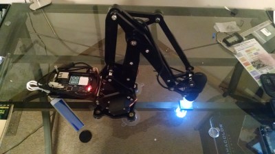
We start with [J. Kha] and Armed Microscope. [J. Kha] was one of the backers of the original uArm over at Kickstarter. He also does quite a bit of work with electronics. After fighting with a cheap USB microscope, he realized he had the perfect platform to control it. Microscopes usually are stationary, with the object being viewed moved on a stage. [J. Kha] turned things upside down by mounting the microscope on his uArm. An Arduino Yun controls the system. The Yun also allows him to stream the microscope’s video over the internet using the mjpg-streamer library. [J. Kha] did have some power issues at first, but he’s got his regulators all sorted out now.
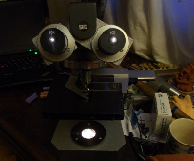
Next we have [andyhull] with Adding a light touch to a “classic” microscope. A lucky dumpster find netted [Andy] a pile of old broken microscopes. From this he was able to build a working classic stereo scope. This was a Gillet & Sibert stereo compound scope. Like most microscopes of its time, the old GS used standard incandescent or halogen lights for illumination. The old bulbs were long gone, and would have been a pain to replace. [Andy] switched his scope over to LED illumination. He ended up using a commercially available LED “bulb” designed to replace type 1157 automotive tail light bulbs. This type of LED is designed to run on 12 volt power which simplifies the wiring. The small LED flashlight in a custom mount also provides a bit of help for opaque subjects.
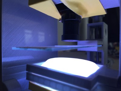
Next up is [Andre Maia Chagas] with Flypi – cheap microscope/experimental setup. Flypi is [Andre’s] entry in the 2106 Hackaday Prize. Flypi is more than just a microscope, it’s a 3D printed data collection and image analysis device for hackers and scientists alike. A Raspberry Pi 2 or 3 controls the show. Images come in through Pi Camera with an M12 lens. The Pi runs some open source Python code allowing it to acquire and analyze images. It also has an Arduino as a co-processor to handle anything a particular experiment may need – like RGB LEDs, heaters, manipulators, you name it. Andre sees Flypi as having uses in everything from fluorescence imaging to optogenetics and thermogenetics.
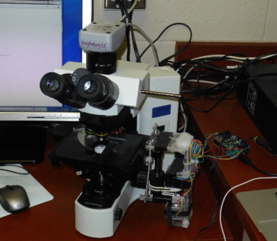
Finally we have [Jarred Heinrich] with Stagmo: Microscope Stage Automator. Positioning samples under high magnification requires a steady hand. Trying to image them makes things even harder. To help with this, microscopes have stages. Fine lead screws manually controlled by knobs allow the user to precisely position any subject. Automated stages are available as well, but they can get quite expensive. [Jarred] recognized that the microscope stage is an X-Y platform like any CNC, laser, or 3D printer. He used an Arduino and a motor shield to control a couple of stepper motors. The motors are coupled to the stage knobs with rubber belts. While the mounting system looks a little wobbly, but it got the job done, and didn’t require any modifications to the microscope itself.
Optical microscopes are just one type of scope you’ll find on Hackaday.io. There are also atomic force microscopes, scanning electron microscopes, and more! I’ll cover those on a future Hacklet. If you want to see more awesome optical microscopy projects, check out our new optical microscope projects list! If I missed your project, don’t be shy, just drop me a message on Hackaday.io. That’s it for this week’s Hacklet. As always, see you next week. Same hack time, same hack channel, bringing you the best of Hackaday.io!
We return once again to the work of Dr. Claude E. Shannon, this time to his Masters thesis on relay switching circuit design. This thesis introduced switching algebra that allows the systematic design and optimization of logical circuits. While Shannon’s work applied to switches and relays, it is equally applicable to all the modern forms of digital circuits. His thesis received widespread notice when published as “A Symbolic Analysis of Relay and Switching Circuits” in 1938. This work built on the Boolean algebra developed by George Boole and an analysis of logic by Augustus De Morgan which these mathematicians published nearly simultaneously in 1847. To some extent, it was the beginning of the age of modern digital logic. Continue reading “Designing Circuits With Switching Algebra”→
In this installment of Minimal MQTT, I’m going to cover two loose ends: one on the sensor node side, and one on the MQTT server side. Specifically, I’ll tackle the NodeMCU’s sleep mode to reduce power and step you through bridging MQTT servers to get your data securely out of your home server and into “the cloud”, which is really just other people’s servers.
If you’re just stepping into this series now, you should really check out the other three posts, where I set up a server, then build up some sensor nodes, and then flesh-out a few ways to control everything from your phone or the web. That’s the coolest material, anyway. This last installment just refines what we’ve built on. Let’s go!
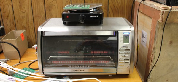
There are a variety of methods for reflowing a circuit board, but they all rely on a single principle: heat up the solder paste (a mixture of flux and solder) until the flux burns off and the solder becomes liquid, and then cool it down. Accomplishing this once or twice is easy; once you’ve played with a hot plate you’ll swear off through hole. Scaling it up and doing it repeatedly with high yield is extremely challenging, though. Continue reading “Tools Of The Trade – Reflow”→
In the early days of broadcast television, national spectrum regulators struggled to reconcile the relatively huge bandwidth required by the new medium with the limited radio spectrum that could be allocated for it. In the USA during the years immediately following World War Two there was only a 12-channel VHF allocation, which due to the constraints of avoiding interference between adjacent stations led to an insufficient number of possible transmitter sites to cover the entire country. This led the FCC in 1949 to impose a freeze on issuing licences for new transmitters, and left a significant number of American cities unable to catch their I Love Lucy or The Roy Rogers Show episodes.
The solution sought by the FCC was found by releasing a large block of UHF frequencies between 470 and 890 MHz from their wartime military allocation, and thus creating the new channels 14 to 83. An experimental UHF pilot station was set up in Bridgeport, Connecticut in 1949, and by 1952 the FCC was ready to release the freeze on new licence applications. The first American UHF station to go on air was thus KPTV in Portland, Oregon, on September 18th of that year.
UHF TV was a very new technology in 1952, and was close to the edge of what could be achieved through early 1950s consumer electronics. Though the 525-line TV standard and thus the main part of the sets were the same as their VHF counterparts, the tuner designs of the time could not deliver the performance you might expect from more recent sets. Their noise levels, sensitivity, and image rejection characteristics meant that UHF TV reception did not live up to some of its promise, and thus a fierce battle erupted between manufacturers all keen to demonstrate the inferiority of their competitors’ products over the new medium.
The video below the break delivers a fascinating insight into this world of claim and counter-claim in 1950s consumer electronics, as Zenith, one of the major players, fires salvos into the fray to demonstrate the superiority of their products over competing models or UHF converters for VHF sets. It’s very much from the view of one manufacturer and don’t blame us if it engenders in the viewer a curious desire to run out and buy a 1950s Zenith TV set, but it’s nonetheless worth watching.
A key plank of the Zenith argument concerns their turret tuner. The turret tuner was a channel selection device that switched the set’s RF front end between banks of coils and other components each preset to a particular TV channel. Zenith’s design had a unique selling point that it could be fitted with banks of components for UHF as well as VHF channels thus removing the need for a separate UHF tuner, and furthermore this system was compatible with older Zenith sets so existing owners had no need to upgrade. Particularly of its time in the video in light of today’s electronics is the section demonstrating the clear advantages of Zenith’s germanium mixer diode over its silicon equivalent. Undeniably true in that narrow application using the components of the day, but not something you hear often.
We are entering a new era of radio technology. A new approach to building radios has made devices like multi-band cell phones and the ubiquitous USB TV receivers that seamlessly flit from frequency to frequency possible. That technology is Software Defined Radio, or SDR.
A idealized radio involves a series of stages. Firstly, an antenna receives the radio signal, converting it into an electrical signal. This signal is fed into a tuned resonator which is tuned to a particular frequency. This amplifies the desired signal, which is then sent to a demodulator, a device which extracts the required information from the carrier signal. In a simple radio, this would be the audio signal that was encoded by the transmitter. Finally, this signal is output, usually to a speaker or headphones.
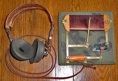
A replica foxhole crystal set. Photo: Bill Jackson
That’s how your basic crystal radio works: more sophisticated radios will add features like filters that remove unwanted frequencies or additional stages that will process the signal to create the output that you want. In an FM radio, for example, you would have a stage after the demodulator that detects if the signal is a stereo one, and separates the two stereo signals if so.
To change the frequency that this radio receives, you have to change the frequency that the resonator is tuned to. That could mean moving a wire on a crystal, or turning a knob that controls a variable capacitor, but there has to be a physical change in the circuit. The same is true of the additional mixing stages that refine the signal. These circuits may be embedded deeply in the guts of the radio, but they are still there. This is the limitation with normal receivers: the radio can’t receive a signal that is outside the range that the resonator circuit can tune to, or change the way it is demodulated and processed. If you want to receive multiple frequency bands or different types of signals, you need to have separate pathways for each band or type of signal, physically switching the signal between them. That’s why you have physical AM/FM switches on radios: they switch the signal from an AM radio processing path to an FM one.
Software Defined Radios remove that requirement. In these, the resonator and demodulator parts of the radio are replaced by computerized circuits, such as analog to digital converters (ADCs) and algorithms that extract the signal from the stream of data that the ADCs capture. They can change frequencies by simply changing the algorithm to look for another frequency: there is no need for a physical change in the circuit itself. So, an SDR radio can be tuned to any frequency that the ADC is capable of sampling: it is not restricted by the range that a resonator can tune to. Similarly, the demodulator that extracts the final signal you want can be updated by changing the algorithm, changing the way the signal is processed before it is output.
This idea was first developed in the 1970s, but it didn’t really become practical until the 1990s, when the development of flexible field-programmable gate array (FPGA) chips meant that there was enough processing power available to create single chip SDR devices. Once programmed, an FPGA has no problem handing the complex tasks of sampling, demodulating and processing in a single device.
Most modern SDRs don’t just use a single chip, though. Rather than directly converting the signal to digital, they use an analog front end that receives the raw signal, filters it and converts it down to a fixed frequency (called the intermediate frequency, or IF) that the ADCs in the FPGA can more easily digitize. This makes it cheaper to build: by converting the frequency of the signal to this intermediate frequency, you can use a simpler FPGA and a cheaper ADC, because they don’t have to directly convert the maximum frequency you want to receive, only the IF. As long as the front end can convert a band of signals down to an intermediate frequency that the FPGA can digitize, the SDR can work with it.
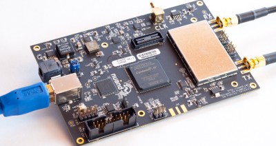
The BladeRF, a modern SDR device that can receive and transmit signals between 300 MHz and 3 GHz
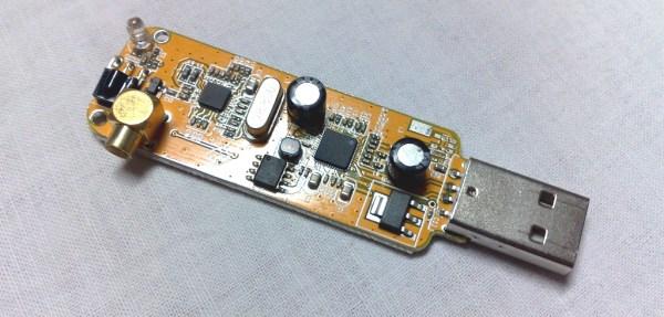
This flexibility means that SDR devices can handle a huge range of signals at relatively low cost. The $420 BladeRF, for instance, can receive and transmit signals from 300 MHz to 3.8 GHz at the same time, while the $300 HackRF One can work with signals from 1 MHz up to an incredible 6 GHz. The ability of the BladeRF to both receive and transmit means that you can use it to build your own GSM phone network, while the low cost of the HackRF One makes it a favorite of radio hackers who want to do things like make portable radio analyzers. Mass produced models are even cheaper: by hacking a $20 USB TV receiver that contains an SDR, you can get a radio that can, with a suitable antenna, do things like track airplanes or receive satellite weather images. And all of this is possible because of the idea of Software Defined Radio.