The Hackaday comments section has become infamous for a recurring theme that goes something like “I don’t know why they used an Arduino, they could have done it with a 555 timer!” If you’ve ever thought the same way, then this post is for you!
What is The Most Important Device In The Universe, then? It’s the Modern Props #195-290-1, a movie prop originally built in the 1970’s. It’s a product of the creative mind of [John Zabrucky] who founded Modern Props in 1977 to serve Sci-Fi television and movie productions that wanted to invent the future with their props. Known for their high quality and impeccable craftsmanship, Modern Props’ products were in demand until the day they closed the doors so that [John] could retire.
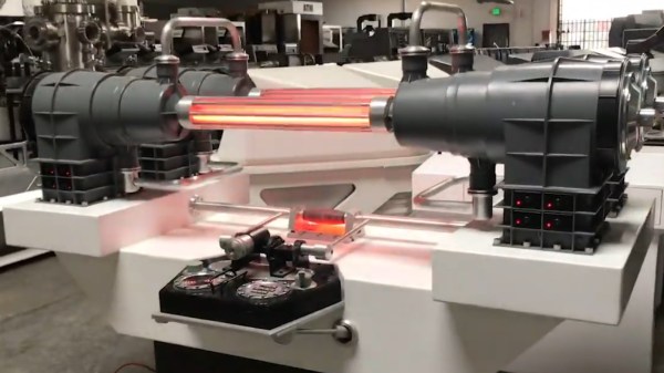
This particular piece is called The Most Important Device In The Universe due to its ubiquity in modern productions that we’ve all heard of: several Star Trek franchises, The Last Starfighter, Knight Rider, Airplane II, Austin Powers, and countless others. The next time you sit down to watch a Sci-Fi show, see if you can spot it! Be sure to check the video below the break to see several examples.
Nobody is sure what The Most Important Device does, aside from the fact that it has red lights that go back and forth. What we do know, thanks to a comment by the man who installed the electronics, [Gene Turnbow], is how it’s powered. [Gene] explained that 45w NPN power transistors drive the neon tubes through step up transformers. The transistors themselves are connected to a 74C4514 demultiplexer, which is itself driven by a 7493 binary counter. What’s the 7493 driven by? You guessed it: the venerable 555 Timer. And so it is that the 555 timer runs The Most Important Device In The Universe.
We did think that [Gene]’s final comment was rather indicative of how much things have changed since the prop was originally built. After explaining the device, he says “These days we would just use an Arduino to do the same job.” Indeed.
Don’t worry, 555 lovers. We’ve got you covered with this Vacuum Tube 555, and and the Trollduino, a 555 on an Arduino Shield. Thanks [Matt K] for the great tip. Don’t forget to submit your favorite hacks to our Tip Line!
Continue reading “The Most Important Device In The Universe Is Powered By A 555 Timer”