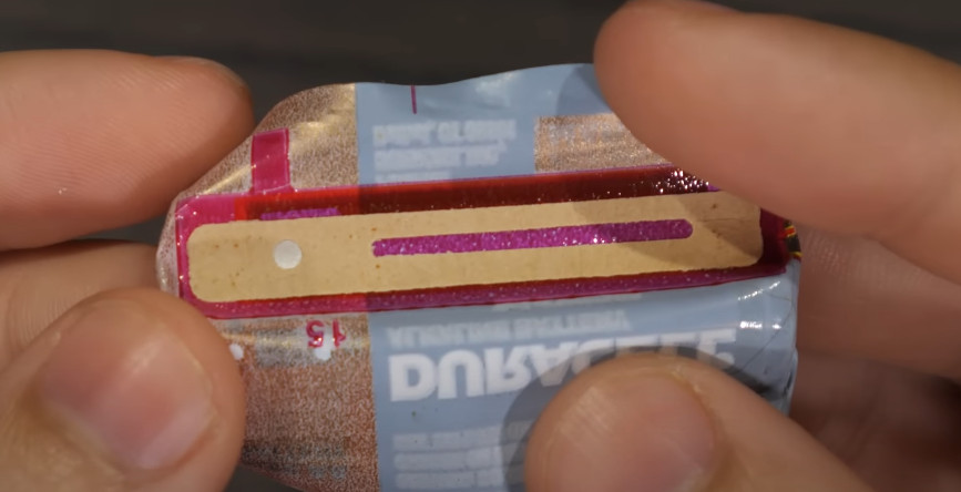
This Open Hardware Li-Ion Charger Skips The TP4056

There’s a good chance that if you build something which includes the ability to top up a lithium-ion battery, it’s going to involve the incredibly common TP4056 charger IC. Now, there’s certainly nothing wrong with that. It’s a decent enough chip, and there are countless pre-made modules out there that make it extremely easy to implement. But if the chip shortage has taught us anything, it’s that alternatives are always good.

So we’d suggest bookmarking this opensource hardware Li-Ion battery charger design from [Shahar Sery]. The circuit uses the BQ24060 from Texas Instruments, which other than the support for LiFePO4 batteries, doesn’t seem to offer anything too new or exciting compared to the standard TP4056. But that’s not the point — this design is simply offered as a potential alternative to the TP4056, not necessarily an upgrade.

[Shahar] has implemented the design as a 33 mm X 10 mm two-layer PCB, with everything but the input and output connectors mounted to the topside. That would make this board ideal for attaching to your latest project with a dab of hot glue or double-sided tape, as there are no components on the bottom to get pulled off when you inevitably have to do some rework.

The board takes 5 VDC as the input, and charges a single 3.7 V cell (such as an 18650) at up to 1 Amp. Or at least, it can if you add a heatsink or fan — otherwise, the notes seem to indicate that ~0.7 A is about as high as you can go before tripping the thermal protection mode.

Like the boilerplate TP4056 we covered recently, this might seem like little more than a physical manifestation of the typical application circuit from the chip’s datasheet. But we still think there’s value in showing how the information from the datasheet translates into the real-world, especially when it’s released under an open license like this.

Researchers Find “Inert” Components In Batteries Lead To Cell Self-Discharge

When it comes to portable power, lithium-ion batteries are where it’s at. Unsurprisingly, there’s a lot of work being done to better understand how to maximize battery life and usable capacity.

Red electrolytic solution, which should normally be clear.

While engaged in such work, [Dr. Michael Metzger] and his colleagues at Dalhousie University opened up a number of lithium-ion cells that had been subjected to a variety of temperatures and found something surprising: the electrolytic solution within was a bright red when it was expected to be clear.

It turns out that PET — commonly used as an inert polymer in cell assembly — releases a molecule that leads to self-discharge of the cells when it breaks down, and this molecule was responsible for the color change. The molecule is called a redox shuttle, because it travels back and forth between the cathode and the anode. This is how an electrochemical cell works, but the problem is this happens all the time, even when the battery isn’t connected to anything, causing self-discharge.

Continue reading “Researchers Find “Inert” Components In Batteries Lead To Cell Self-Discharge”

Copy And Paste Lithium Battery Protection

Lithium batteries have, nearly single-handedly, ushered in the era of the electric car, as well as battery energy storage of grid power and plenty of other technological advances not possible with older battery chemistries. There’s just one major downside: these lithium cells can be extremely finicky. If you’re adding one to your own project you’ll have to be extremely careful to treat them exactly how they are designed to be treated using something like this boilerplate battery protection circuit created by [DIY GUY Chris].

The circuit is based around the TP4056 integrated circuit, which handles the charging of a single lithium cell — in this design using supplied power from a USB port. The circuit is able to charge a cell based on the cell’s current charge state, temperature, and a model of the cell. It’s also paired with a DW01A chip which protects the cell from various undesirable conditions such as over-current, overcharge, and over-voltage.

The best thing about this design isn’t the design itself, but that [DIY GUY Chris] built the circuit schematic specifically to be easily copied into PCB designs for other projects, which means that lithium batteries can more easily be integrated directly into his other builds. Be sure to check out our primer on how to deal with lithium batteries before trying one of your own designs, though.

Continue reading “Copy And Paste Lithium Battery Protection”

A cartoon vehicle is connected to two wires. One is connected to an illustrated Li anode and the other to a γ-sulfur/carbon nanofiber electrode. Lithium ions and organic carbonate representations float between the two electrodes below the car. A red dotted line between the electrodes symbolizes the separator.

Lithium Sulfur Battery Cycle Life Gets A Boost

Lithium sulfur batteries are often touted as the next major chemistry for electric vehicle applications, if only their cycle life wasn’t so short. But that might be changing soon, as a group of researchers at Drexel University has developed a sulfur cathode capable of more than 4000 cycles.

Most research into the Li-S couple has used volatile ether electrolytes which severely limit the possible commercialization of the technology. The team at Drexel was able to use a carbonate electrolyte like those already well-explored for more traditional Li-ion cells by using a stabilized monoclinic γ-sulfur deposited on carbon nanofibers.

The process to create these cathodes appears less finicky than previous methods that required tight control of the porosity of the carbon host and also increases the amount of active material in the cathode by a significant margin. Analysis shows that this phase of sulfur avoids the formation of intermediate fouling polysulfides which accounts for it’s impressive cycle life. As the authors state, this is far from a commercial-ready system, but it is a major step toward the next generation of batteries.

We’ve covered the elements lithium and sulfur in depth before as well as an aluminum sulfur battery that could be big for grid storage.

Fool A Drone With A Fixed Battery

Lithium-ion and lithium-polymer rechargeable batteries have given us previously impossible heights of electronics power and miniaturization, but there’s a downside they have brought along with them. When a battery pack has to contain electronics for balancing cells, it’s very easy for a manufacturer to include extra functions such as locking down the battery. Repair a battery, replace cells, or use a third-party battery, and it won’t work. [Zolly] has this with a DJI Mavic Mini pack, and shares with us a method for bypassing it.

The pack talks to the multi-rotor with a serial line, and the hack involves interrupting that line at the opportune moment to stop it telling its host that things are amiss. Which is a good start — but we can’t help hacing some misgivings around the rest of the work. Disconnecting the balance line between the two cells and fooling the Battery Management System (BMS) with a resistive divider seems to us like a recipe of disaster, as does bypassing the protection MOSFETs with a piece of wire. It may work, and in theory the cells can be charged safely with an external balance charger, but we’re not sure we’d like to have a pack thus modified lying around the shop.

It does serve as a reminder that BMS boards can sometimes infuriatingly lock their owners out. We once encountered this with a second-generation iBook battery that came back to life after a BMS reset, but it’s still not something to go into unwarily. Read our guide to battery packs and BMS boards to know more.

Continue reading “Fool A Drone With A Fixed Battery”

Showing a USB-C tester running the DingoCharge script, charging a battery pack at 7V. To the right is a battery pack being charged, and a USB-C charger doing the charging.

Use USB-C Chargers To Top Up Li-Ion Packs With This Hack

In USB-C Power Delivery (PD) standard, the PPS (Programmable Power Supply) mode is an optional mode that lets you request a non-standard voltage from a charger, with the ability to set a current limit of your choice, too. Having learned this, [Jason] from [Rip It Apart] decided to investigate — could this feature be used for charging Li-Ion battery packs, which need the voltage and current to vary in a specific way throughout the charging process? Turns out, the answer is a resounding “yes”, and thanks to a USB-C tester that’s programmable using Lua scripts, [Jason] shows us how we can use a PPS-capable USB-C charger for topping up our Li-Ion battery packs, in a project named DingoCharge.

The wonderful write-up answers every question you have, starting with a safety disclaimer, and going through everything you might want to know. The GitHub repo hosts not only code but also full installation and usage instructions.

DingoCharge handles more than just Li-Ion batteries — this ought to work with LiFePO4 and lithium titanate batteries, too.  [Jason] has been working on Ni-MH and lead-acid support. You can even connect an analog output thermal sensor and have the tester limit the charge process depending on the temperature, showing just how fully-featured a solution the DingoCharge project is.

The amount of effort put into polishing this project is impressive, and now it’s out there for us to take advantage of; all you need is a PPS-capable PSU and a supported USB-C tester. If your charger’s PPS is limited by 11V, as many are, you’ll only be able to fully charge 2S packs with it – that said, this is a marked improvement over many Li-Ion solutions we’ve seen. Don’t have a Li-Ion pack? Build one out of smartphone cells! Make sure your pack has a balancing circuit, of course, since this charger can’t provide any, and all will be good. Still looking to get into Li-Ion batteries? We have a three-part guide, from basics to mechanics and electronics!

Fritzing diagram of connections between the Wemos D1 board, the TP4056 board, the pushbutton and the LiIon battery

Battery-Powered ESP8266 Sensor? Never Been Simpler

Say, you’re starting your electronics journey with a few projects in mind. You have an ESP8266 board like the Wemos D1, a Li-Ion battery, you want to build a small battery-powered sensor that wakes up every few minutes to do something, and you don’t want to delve into hardware too much for now. Well then, does [Mads Chr. Olesen] have a tutorial for you! Here, you’ll learn the quick and easy way to get your sensor up and running, learn a few tricks for doing sleep Arduino environment, and even calculate how long your specific battery could last. Continue reading “Battery-Powered ESP8266 Sensor? Never Been Simpler”