Improving OLED VU Meters With A Little Physics

Last month we featured a project that aimed to recreate the iconic mechanical VU meter with an Arduino and a common OLED display. It was cheap and easy to implement, and promised to bring a little retro style to your otherwise thoroughly modern project.

[sjm4306] liked the idea, but thought it was a tad too stiff. So he’s been experimenting with adding some physics to the meter’s virtual needle to better approximate the distinctive lag and overshoot that’s part and parcel of analog indicators. Obviously it’s something that can only be appreciated in motion, so check out the video below for an up-close look at his quasi-retro indicator.

Unfortunately there’s no code for you to play with right now, but [sjm4306] says he’ll release it on the project’s Hackaday.IO page once he’s cleaned things up a bit. We know it will take more than a few wiggling pixels to pry real analog indicators out of some hacker’s tool boxes, but anything that helps improve the digital approximation of this sort of vintage hardware is a win in our book. Continue reading “Improving OLED VU Meters With A Little Physics”

Wristwatch PCB Swaps Must Be In The Air

Are we seeing more wristwatch PCB swapping projects because more people are working on them, or because we saw one and they’re on our mind? The world may never know, but when it comes to design constraints, there’s a pretty fun challenge here both in fitting your electronic wizardry inside the confines of an injection molded case, and in the power budget to make your creation run on a sippy straw of battery power.

Just this morning we came across [Joey Castillo’s] sensor-watch project. He chose the Casio F-91W as the donor wristwatch. It’s got that classic Casio look of a segment LCD display capable of displaying hours, minutes, and seconds, as well as day and date. But the added bonus is that we know these have decent water resistance while still providing three buttons for user input. Sure, it’s less buttons than the pink calculator watch we saw [Dave Darko] working on earlier in the week, but which would you trust in the pool?

Replacement PCB sized to use the same battery contact and CR2016 for power [via @josecastillo]
We see that [Joey] also chose to use the ATSAML22 microcontroller and sheds some light on why: it includes a built-in segment LCD controller! If you’re a peripheral geek like us, you can read about the SLCD controller on page 924 of the datasheet (PDF), it’s a whole datasheet onto itself.

The sensor part of the sensor-watch is a flex PCB breakout that allows you to swap in whatever sensor fits your needs. The first to be reflowed at [Joey’s] bench is a BME280 humidity sensor, which is most obviously useful for the included temperature measurements, but maybe it could also alarm at moisture ingress? [Joey] says you can swap in other parts as long as they’re in the QFN or LGA size range. We think an IMU is in order since there’s a lot of fun interaction there like the watch reacting to being positioned in front of your face, or to take tap-based inputs.

We think beginning with a donor watch is brilliant since pulling off a case, especially one that keeps water out, is 97% of the battle. But when your UI is unique to the watch world, sometimes you need to start from scratch like this wooden word clock wristwatch.

Raspberry Pi Pico Used As A Transputer

You can’t fake that feeling when a $4 microcontroller dev board can stand in as cutting-edge 1980s technology. Such is the case with the working transputer that [Amen] has built using a Raspberry Pi Pico.

For a thorough overview of the transputer you should check out [Jenny List’s] longer article on the topic but boiled down we’re talking about a chip architecture mostly forgotten in time. Targetting parallel computing, each transputer chip has four serial communication links for connecting to other transputers. [Amen] has wanted to play with the architecture since its inception. It was expensive back then and today, finding multiple transputers is both difficult and costly. However, the RP2040 chip found on the Raspberry Pi Pico struck him as the perfect way to emulate the transputer design.

The RP2040 chip on the Pico board has two programmable input/output blocks (PIOs), each with four state machines in them. That matches up perfectly with the four transputer links (each is bi-directional so you need eight state machines). Furthermore, the link speed is spec’d at 10 MHz which is well within the Pico’s capabilities, and since the RP2040 runs at 133 MHz, it’s conceivable that an emulated core can get close to the 20 MHz top speed of the original transputers.

Bringing up the hardware has been a success. To see what’s actually going on, [Amen] sourced some link adapter chips (IMSC011), interfacing them through an Arduino Mega to a computer to use the keyboard and display. The transputer architecture allows code to be loaded via a ROM, or through the links. The latter is what’s running now. Future plans are to figure out a better system to compile code, as right now the only way is by running the original INMOS compiler on DOS in a VM.

Listen to [Amen] explain the project in the first of a (so far) six video series. You can find the links to the rest of those videos on his YouTube channel.

Continue reading “Raspberry Pi Pico Used As A Transputer”

Knowing The Bits And Bytes That Make Images Live In Memory

We know we’re living in the future because there’s hi-resolution, full color images plastered on every high-density screen in sight. Of course this comes at a cost, one that’s been hidden away by the myriad improvements in the way we digitally represent those pretty pixels and how we push them to the screens. Nobody thinks about this, except those who are working behind the screen to store and light up those pixels. And hey, chances are that’ll be you some day. Time to learn a bit more about image encoding!

Test renders illustrate the time savings from premultiplied alpha formats

[Scott W Harden] put together a succinct primer on representing images in memory. It focuses on the basics of how images are stored: generally with the B before the G, sometimes including an alpha (transparent) channel, and with a number of different bit depths. Having these at the front of your mind is crucial for microcontroller projects, where deciding what types of images to support is often limited by the amount of memory available for frame buffers, and the capabilities of the screen chosen as the device’s display.

Speaking of display specifics, [Scott] shares some detail about mapping the memory to the dimensions of your screen. If the byte count of pixel data doesn’t line up nicely with the dimensions of the screen, padding the rows out may help in the processing overhead it takes to get those pixels onto the screen. He also has some tips about “premultiplied alpha” which makes the transparency calculation a part of the image itself, rather than demanding this be done when trying to update the screen. Running a test in C# on one million frame renders shows the type of savings you can expect.

Decades of trial and error landed us with these schemes. Looking back is literally an archaeology project, as one hacker discovered when trying to get a set of digital images off of a floppy from a 1990s photo processing service.

Working LEGO Space Computers Are A Chip Off The Old Block

We all have our favorite classic LEGO bricks, and wouldn’t be surprised if one or more of the various space computers showed up on pretty much everyone’s list. [dyoramic] loves them so much that they built two different working versions that do different things.

The first one is about six times the size of the original brick. Inside the 3D printed case is an ESP32 and a 1.5″ OLED display. [dyoramic] wired up the top six buttons as inputs and the rest are just for looks. The screen defaults to the classic white cross on green that just sits there looking legit. But start pushing buttons and you’ll find other modes — the cross becomes a radar screen in one, the computer spits out space facts in another, there’s a falling bricks game, and finally, a time and date screen.

The second LEGO space computer build is even bigger — both were designed around the size of their screens. It has a Raspi 4 and shows a dashboard with the weather, time, date, latest xkcd, and a few cryptocurrency prices. [dyoramic] has an even bigger version in the works that will use a 720 x 720 screen and a handful of brown key switches as inputs. We can’t wait to see that one! For now, check out the build and demo of the first two after the break.

What can’t you do with LEGO? It feels like we’ve seen it all, from cameras to microscopes to continuously variable transmissions. Wouldn’t you love to drive one of those around the block?

Continue reading “Working LEGO Space Computers Are A Chip Off The Old Block”

Streaming Video From A Mouse

The first optical mice had to be used on a specially printed mousepad with a printed grid that the four-quadrant infrared sensor could detect. Later, mice swapped the infrared sensor for an optoelectric module (essentially a tiny, very low-resolution camera) and a powerful image processing. [8051enthusiast] was lying in bed one day when they decided to crack the firmware in their gaming mouse and eventually start streaming frames from the camera inside.

Step one was to analyze the protocol between the mouse and the host machine. Booting up a Windows VM and Wireshark allowed him to capture all the control transfers to the USB controller. Since it was a “programmable” gaming mouse that allowed a user to set macros, [8051enthusiast] could use the control transfers that would normally query that macro that had been set to return the memory at an arbitrary location. A little bit of tinkering later, and he now had a dump of the firmware. Looking at the most abundant bytes, it seems to match a profile similar to the Intel 8051. In a fascinating blur of reverse engineering, he traced the main structure of the program back from the function that sets the LED colors for the scroll wheel (which is dependent on the current DPI setting). Unfortunately, the firmware prevented the same macro mechanism from writing to arbitrary locations.

Looking through the code, a good old buffer overflow exploit seemed possible, but it caused the system to reset via watchdog. So he took another approach, invoking recovery mode and loading an entirely new firmware on the device, which a set_report control transfer can invoke.

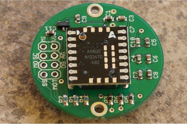
Next, he moved onto the ADNS-9800 optical sensor (pictured in the top image provided by JACK Enterprises), which had a large encrypted blob in the firmware. Some poking around and deduction lead to a guess that the optical sensor was another 8051 system. With some clever reasoning and sheer determination, [8051enthusiast] was able to crack the XOR stream cipher encryption with a program that showed him versions of the disassembled assembly and allowed him to pick the one that was the most likely. With the firmware decrypted, he was able to see the encryption code and confirm his deducted algorithm.

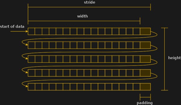
With the sensor now cracked open, it was onto the 30 x 30 240 fps video stream. The sensor communicates over SPI, and the USB controller has to bit-bang the connection as it doesn’t have the hardware. Putting two custom firmware images on with a few extra functions was easy enough, but the 7 fps was somewhat lacking. The first optimization was loop unrolling and removing some sleeps in the firmware, which bought it up to 34 fps. By measuring the cycle counts of individual instructions, he was able to find some alternatives such as a mov instead of a setb that took one less cycle. Going from a 17 cycle loop to an 11 cycle loop and some other optimizations gave him 54 fps. Not content to stop there, he modified the ADNS-9800 firmware to continuously sample rather than waiting for the USB controller to finish processing. While this yielded 100 fps, there was still more to do: image compression. At a whopping 230 fps, [8051enthusiast] decided to call it done.

However, there was one last thing he wanted to do: control the mouse with the video stream. Writing some image processing into his Python-based program that received the image files allowed him to use the mouse, however impractically.

All in all, it’s an incredible journey by [8051enthusiast], and we would highly recommend reading the whole journey yourself. This isn’t the first time he’s modified the firmware of 8051-based devices, such as modifying the firmware of the WiFi chipset in his laptop.

[Thanks to JACK Enterprises over at Tindie for the use of the image of an ADNS9000].
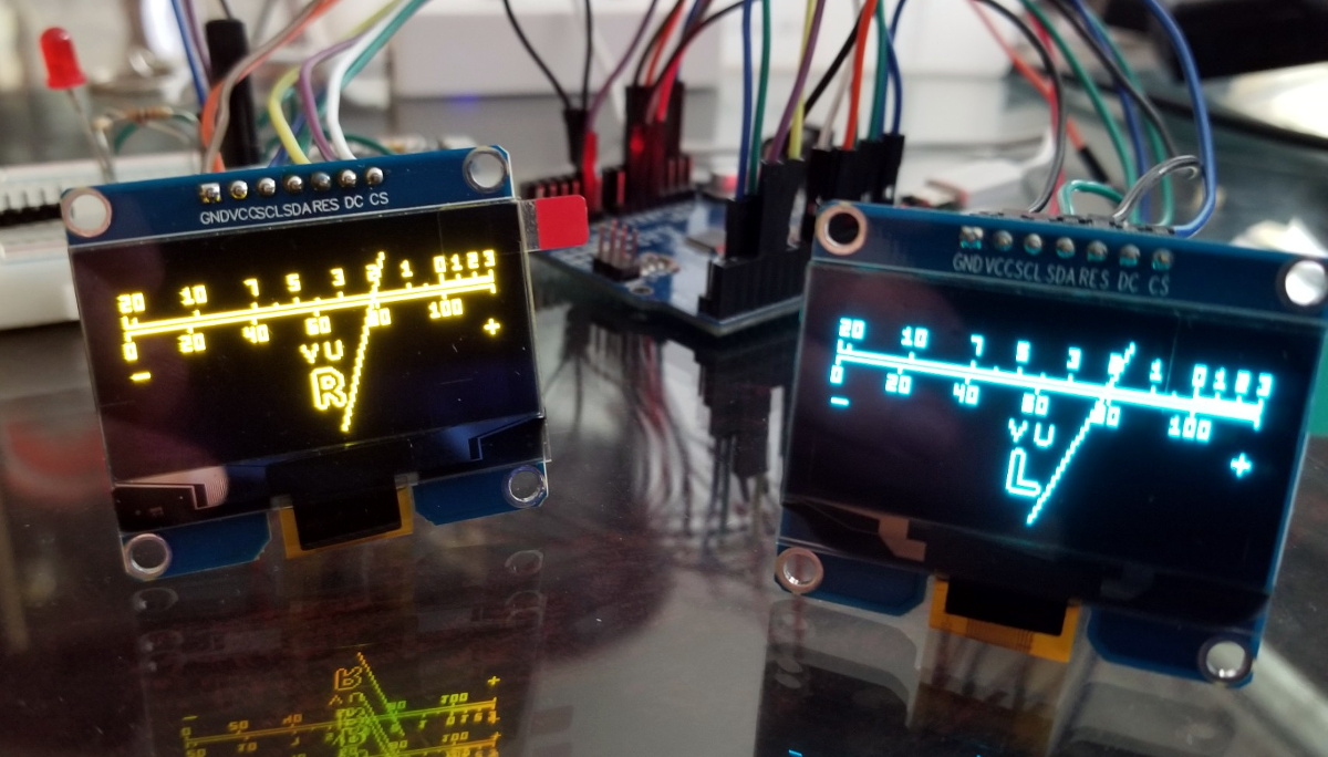
 

Here’s How To Sniff Out An LCD Protocol, But How Do You Look Up The Controller?

Nothing feels better than getting a salvaged component to do your bidding. But in the land of electronic displays, the process can quickly become a quagmire. For more complex displays, the secret incantation necessary just to get the things to turn on can be a non-starter. Today’s exercise targets a much simpler character display and has the added benefit of being able to sniff the data from a functioning radio unit.

When [Amen] upgraded his DAB radio he eyed the 16×2 character display for salvage. With three traces between the display and the controller it didn’t take long to trace out the two data lines using an oscilloscope. Turing on the scope’s decoding function verified his hunch that it was using I2C, and gave him plenty of data to work from. This included a device address, initialization string, and that each character was drawn on screen using two bytes on the data bus.

He says that some searching turned up the most likely hardware: a Winstar WO1602I-TFH- AT derived from an ST7032 controller. What we’re wondering is if there is a good resource for searching this kind of info? Our go-to is the LCD display and controller reference we covered here back in March. It’s a great resource, but turns up bupkis on this particular display. Are we relegated to using DuckDuckGo for initialization strings and hoping someone’s published a driver or a logic dump of these parts in the past, or is there a better way to go about this? Let us know in the comments!