Even when you build something really, really nice, there’s always room for improvement, right? As it turns out for this attempted upgrade to a DIY spot welder, not so much.
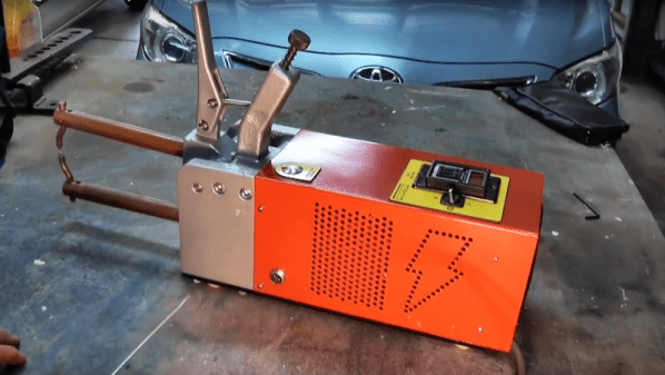
You’ll no doubt recall [Mark Presling]’s remarkably polished and professional spot welder build that we featured some time ago. It’s a beauty, with a lot of thought and effort put into not only the fit and finish but the function as well. Still, [Mark] was not satisfied; he felt that the welder was a little underpowered, and the rewound microwave oven transformer was too noisy. Taking inspiration from an old industrial spot welder, he decided to rebuild the transformer by swapping the double loop of battery cable typically used as a secondary with a single loop of thick copper stock. Lacking the proper sized bar, though, he laminated multiple thin copper sheets together before forming the loop. On paper, the new secondary’s higher cross-sectional area should carry more current, but in practice, he saw no difference in the weld current or his results. It wasn’t all bad news, though — the welder is nearly silent now, and the replaced secondary windings were probably a safety issue anyway, since the cable insulation had started to melt.
Given [Mark]’s obvious attention to detail, we have no doubt he’ll be tackling this again, and that he’ll eventually solve the problem. What suggestions would you make? Where did the upgrade go wrong? Was it the use of a laminated secondary rather than solid bar stock? Or perhaps this is the best this MOT can do? Sound off in the comments section.
Continue reading “Fail Of The Week: The Spot Welder Upgrade That Wasn’t”