For as popular as the piano is in music studios, homes, and schools, it almost defies logic. Compared to a guitar, harmonica, or drum set, pianos are incredibly complex machines that can have somewhere on the order of 8,000 moving parts in a case that can easily weigh hundreds of pounds and which often responds quite poorly to seasonal changes in temperature and humidity. But for putting up with all of these downsides, musicians are rewarded with an instrument that uniquely responds to touch, style, and emotion. A big reason for that is that mechanical complexity, and [Super Valid Designs] is attempting to bring that design to a drum set.
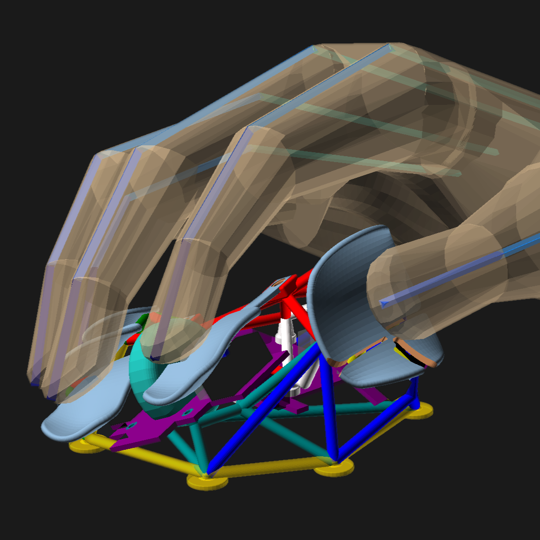
Compared to the complex machinery that connects the movement of a piano’s key to its hammer striking a string, a kick drum pedal is much simpler. It can only bounce off of the drum or get “buried” where the beater remains pressed up against the drum after hitting it. [Super Valid Designs] wanted something with a bit more finesse and control, so he first 3D printed a mechanism that throws the beater towards the drum head and then disconnects it mechanically from the pedal, so that it rebounds even if the pedal stays depressed. The next steps were more difficult, which involved making sure the mechanism reset itself in a repeatable way, without making too much noise of its own. This involved trying out a few different ideas and printing a massive amount of subtly different linkages, but in the end he’s left with a machine that nearly replicates all of the parts of a piano’s escapement,
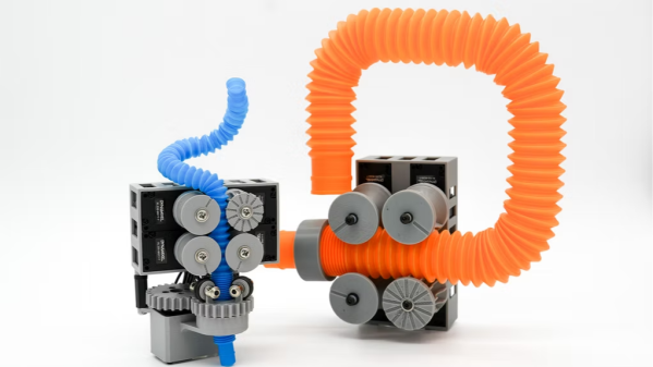
The end goal of this project wasn’t simply to reproduce piano mechanisms on a drum set, though. [Super Valid Designs] hopes to make a kick drum that’s much smaller than those found in traditional kits, and since smaller drums respond poorly when the beater remains on or near the drum after striking it, a mechanism like this will dramatically improve the performance of the smaller drum and help reduce the requirement for perfect technique. And, maybe in 50 years or so, these types of escapements will take over the drumming world just like the piano escapement took over keyboards after its invention in the 1700s. Some simpler piano actions have been built before, but the complexity seems to be a requirement for all of the tasks they need to do whether its for a piano or a drum.