If you’ve ever flown or watched anyone fly a racing drone for any length of time, you know that crashes are just part of the game and propellers are consumables. [Adam] knows this all to well, decided to experiment with combining multiple broken propellers into one with a 3D printed hub.
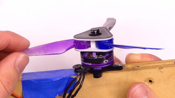
A damaged propeller will often have one blade with no damage, still attached to the hub. [Adam] trimmed the damaged parts of a few broken props, and set about designing a 3D printed hub to attach the loose blades together. The hubs were designed let the individual blades to move, and folding out as the motors spin up, similar to the props on many photography drones.
Once [Adam] had the fit of the hubs dialed in, he mounted a motor on a piece of wood and put the reborn propellers through their paces. A few hubs failed in the process, which allowed [Adam] to identify weak points and optimise the design. This sort of rapid testing is what 3D printing truly excels at, allowing test multiple designs quickly instead of spending hours in CAD trying to foresee all the possible problems.
He then built a test drone from parts he had lying around and proceeded with careful flight testing. The hubs were thicker than standard propellers so it limited [Adams] motor choices to ones with longer shafts. Flight testing went surprisingly well, with a hub only failing after [Adam] changed the battery from a 3 cell to a 4 cell and started with some aerobatics. Although this shows that the new props are not suitable for the high forces from racing or aerobatics/freestyle flying, they could probably work quite well for smoother cruising flights. The hubs could also be improved by adding steel pins into the 3D printed shafts, and some carefully balancing the assembled props.
Continue reading “Combine Broken Drone Propellers For A Second Spin”