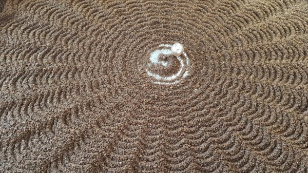
The patience and precision involved with drawing geometric patterns in sand is right up a robot’s alley, and demonstrating this is [rob dobson]’s SandBot, a robot that draws patterns thanks to an arm with a magnetically coupled ball.
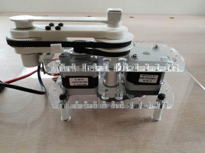
SandBot is not a cartesian XY design. An XY frame would need to be at least as big as the sand table itself, but a SCARA arm can be much more compact. Sandbot also makes heavy use of 3D printing and laser-cut acrylic pieces, with no need of an external frame.
[rob]’s writeup is chock full of excellent detail and illustrations, and makes an excellent read. His previous SandBot design is also worth checking out, as it contains all kinds of practical details like what size of ball bearing is best for drawing in fine sand (between 15 and 20 mm diameter, it turns out. Too small and motion is jerky as the ball catches on sand grains, and too large and there is noticeable lag in movement.) Design files for the SCARA SandBot are on GitHub but [rob] has handy links to everything in his writeup for easy reference.
Sand and robots (or any moving parts) aren’t exactly a natural combination, but that hasn’t stopped anyone. We’ve seen Clearwalker stride along the beach, and the Sand Drawing Robot lowers an appendage to carve out messages in the sand while rolling along.