A Real-Time Networked VU Running On The ESP8266

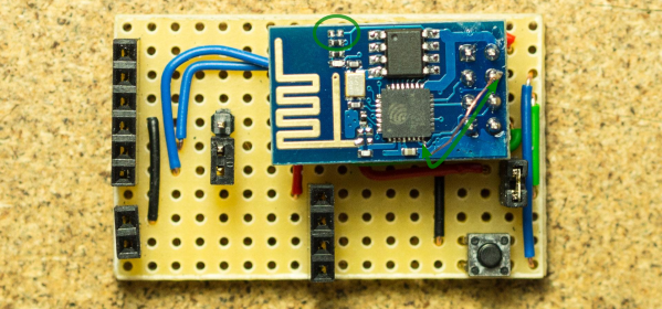
Even though the ESP8266 WiFi chipsets are really cheap (and can be somewhat challenging to work with), they still pack a lot of processing power. For instance, [Mr.jb.swe] took one of these modules and made a stand-alone live VU meter with WS2812B LED strip. The VU runs entirely on the ESP chip, without any additional microcontroller. It’s an example we think a lot of projects could follow to do away with unused horsepower (extra microcontrollers) sometimes used to avoid programming directly on the ESP. The stuff you can do with these modules is wild… did you see this WiFi signal strength mapping project?

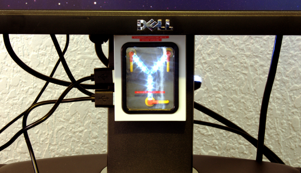
The ESP chipset acts as a UDP client which receives packets from a WinAmp plugin that [Mr.jb.swe] wrote. The plugin continuously calculates the dB of whatever track is playing and streams it over WiFi to his ESP8266. He also mentions that the ADC of the ESP chipset could be used to sample audio as well, although that pretty much eliminates the need for WiFi.

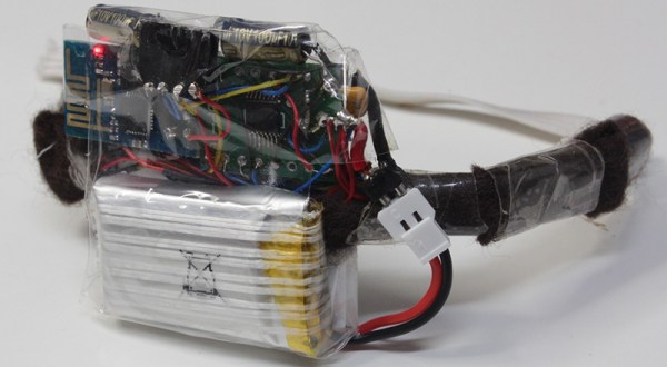
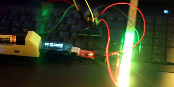
The whole setup is very responsive even though the processor is parsing UDP messages, driving the WS2812 strip, and driving a small OLED display for debug—and it doesn’t even use a separate microcontroller. [Mr.jb.swe] also posted snippets of his code to get you started on your own project. Check out the videos after the break to see it in action.

Continue reading “A Real-Time Networked VU Running On The ESP8266”

Flux Capacitor

Great Scott! A Flux Capacitor Notification Light

If you are into your social media, then you probably like to stay updated with your notifications. [Gamaral] feels this way but he wasn’t happy with the standard way of checking the website or waiting for his phone to alert him. He wanted something a little more flashy. Something like a flux capacitor notification light. This device won’t send his messages back in time, but it does look cool.

He started with an off-the-shelf flux capacitor USB charger. Normally this device just looks cool when charging your USB devices. [Gamaral] wanted to give himself more control of it. He started by opening up the case and replacing a single surface mount resistor. The replacement component is actually a 3.3V regulator that happens to be a similar form factor as the original resistor. This regulator can now provide steady power to the device itself, as well as a ESP8266 module.

The ESP8266 module has built-in WiFi capabilities for a low price. The board itself is also quite small, making it suitable for this project. [Gamaral] used just two GPIO pins. The first one toggles the flux circuit on and off, and the second keeps track of the current state of the circuit. To actually trigger the change, [gamaral] just connects to the module via TCP and issues a “TIME CIRCUIT ON/OFF” command. The simplicity makes the unit more versatile because an application running on a PC can actually track various social media and flash the unit accordingly.

Mapping WiFi Signals In 3 Dimensions

[Charles] is on a quest to complete ever more jaw-dropping hacks with the popular low-cost ESP8266 WiFi modules. This week’s project is plotting WiFi received signal strength in 3D space. While the ESP8266 is capable of providing a Received Signal Strength Indication (RSSI), [Charles] didn’t directly use it. He wrote a simple C program on his laptop to ping the ESP8266 at around 500Hz. The laptop would then translate the RSSI from the ping replies to a color value, which it would then send to the ESP8266. Since the ESP8266 was running [Charles’] custom firmware (as seen in his WiFi cup project), it could directly display the color on a WS2812 RGB LED.

The colors seemed random at first, but [Charles] noticed that there was a pattern. He just needed a way to visualize the LED over time. A single frame long exposure would work, but so would video. [Charles] went the video route, creating SuperLongExposure, an FFMPEG-based tool which extracts every video frame and composites them into a single frame. What he saw was pretty cool – there were definite stripes of good and bad signal.

wifiPOVThumb
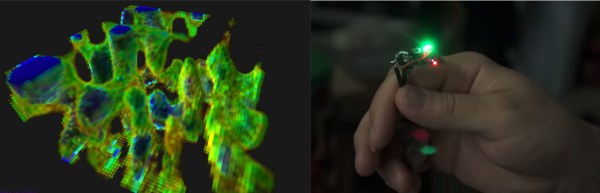
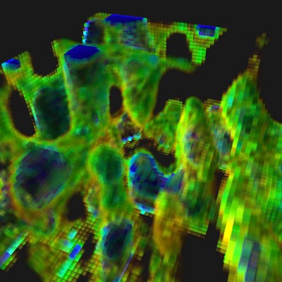
Armed with this information, [Charles] went for broke and mounted his ESP8266 on a large gantry style mill. He took several long exposure videos of a 360x360x180mm area. The videos were extracted into layers. The whole data set could then be visualized with Voxeltastic, [Charles’] own HTML5/WEBGL based render engine. The results were nothing short of amazing. The signal strength increases and decreases in nodes and anti-nodes which correspond to the 12.4 cm wavelength of a WiFi signal. The final render looks incredibly organic, which isn’t completely surprising. We’ve seen the same kind of image from commercial antenna simulation characterization systems.

Once again [Charles] has blown us away, we can’t wait to see what he does next!

Continue reading “Mapping WiFi Signals In 3 Dimensions”

A Haptic Bracelet For Physical Computing

[Tinkermax] has been reading about the Internet of Things and wearable computing and decided it was time for him to have a go at building a device that turned computing physical. The result is a vibrating wristband that connects his sense of touch to the Internet.

The electronics for this haptic wristband are a mix of old and new technology. The radio and microcontroller come from an ESP-8266 module that was programmed with [Mikhail Grigorev]’s unofficial SDK. The mechanics for the wrist-mounted computer consist of six pager motors mounted around the wrist. These are driven somewhat ingeniously by a TLC5917 LED driver chip. This meant the ESP would only need to use two of its GPIOs to control six motors.

Right now the software is simple enough; just a web page, a few buttons, and the ability to buzz any of the pager motors on the wrist band over the Internet. Now it’s just a question of making this wearable useful, but connecting each pager motor to different notifications – a new email, a new SMS, or some emergency on the Internet – should be pretty easy.

Video below.

Continue reading “A Haptic Bracelet For Physical Computing”

Castellated Breakout Is Pitchin’ Brilliant!

Radio, WiFi and similar modules are getting smaller by the day. Trouble is, they end up having non-DIY-friendly, odd pitch, mounting pads. Sometimes, though, simple hacks come around to help save the day.

[Hemal] over at Black Electronics came up with a hack to convert odd-pitch modules to standard 2.54mm / 0.1″. The process looks simple once you see the detailed pictures on his blog. He’s using the technique to add 2mm pitch modules like the ESP8266 and XBee by soldering them to standard perf board. Once they are hooked to the board, just add a row of male header pins, trim the perf board and you’re done. Couldn’t get simpler.

Another technique that we’ve seen is to solder straight across the legs and cut the wire afterward. That technique is also for protoyping board, but custom-sized breakout boards are one good reason to still keep those etchants hanging around. If you have other techniques or hacks for doing this, let us know in the comments.

Hack Allows ESP-01 To Go To Deep Sleep

The ESP-01 module based on the ESP8266 is all the rage with IoT folks at the moment – and why not. For about 5 bucks, it can’t be beat on price for the features it offers. The one thing that such radios do a lot is suck power. So, it’s no surprise that ways to cut down on the juice that this device consumes is top priority for many people. [Tim] figured out a simple hardware hack to get the ESP-01 to go to deep sleep, effectively reducing its current draw to 78uA – low enough to allow battery powered deployment.

While [Tim] was working on understanding the ESP8266 tool chain (NodeMCU firmware > Lua interpreter > ESPlorer IDE), he realized that some essential pins weren’t accessible on the ESP-01 module. [Tim] built a Dev board on perf board that let him access these pins and also added some frills while at it. We’re guessing he (or someone else) will come up with a proper PCB to make things easier. But the real hack is on the ESP-01 module itself. [Tim] needed to hardwire the ‘post-sleep-reset-pin’ on the MCU to the Reset terminal. That, and also pry off the indicator LED’s with a screw driver! That sounds a bit drastic, and we’d recommend pulling out your soldering iron instead. If you’re one of the unlucky one’s to receive the “magic smoke” releasing ESP8266 modules, then you don’t need the LED anyway.

Alarm1

Adding WiFi And SMS To An Alarm System

[Don] wanted to bring his alarm system into the modern age. He figured that making it more connected would do the trick. Specifically, he wanted his alarm system to send him an SMS message whenever the alarm was tripped.

[Don] first had to figure out a way to trigger an event when the alarm sounds. He found a screw terminal that lead to the siren. When the alarm is tripped, this screw terminal outputs 12V to enable the siren. This would be a good place to monitor for an alarm trip.

[Don] is using an Arduino nano to monitor the alarm signal. This meant that the 12V signal needed to be stepped down. He ran it through a resistor and a Zener diode to lower the voltage to something the Arduino can handle. Once the Arduino detects a signal, it uses an ESP8266 WiFi module to send an email. The address [Don] used is the email-to-SMS address which results in a text message hitting his phone over the cell network.

The Arduino also needed power. [Don] found a screw terminal on the alarm system circuit board that provided a regulated 12V output. He ran this to another power regulator board to lower the voltage to a steady 5V. This provides just the amount of juice the Arduino needs to run, and it doesn’t rely on batteries. [Don] provides a good explanation of the system in the video below. Continue reading “Adding WiFi And SMS To An Alarm System”