An OpenSCAD Library For All Your CNC Cutting Needs

While there’s always the edge case, there’s a strong likelihood that if you’re using OpenSCAD, you’re probably working on a CAD model that you intend to 3D print at some point. Of course that’s not to say this is all you can do in OpenSCAD, but it’s arguably what it does best. If you wanted to make artistic models, or maybe render what your new kitchen will look like, there are other tools better suited to such tasks.

But thanks to lasercut.scad, a library that [Brendan Sleight] has been working on for the last several years, we might have to reconsider our preconceived dimensional notions. Instead of designing parts for 3D printing, his library is all about creating parts intended for subtractive manufacturing. Originally (as the name implies) it was geared towards laser cutting, but the project has since evolved to support CNC routers, vinyl cutters, and pretty much anything else that can follow a DXF file.

This “clip” joint is great for acrylic.

The library has functions for creating the standard tricks used to build things from laser-cut pieces, like finger joints, captive nuts, and assembly tabs. If it was something you once saw holding together an old wooden 3D printer kit back in the day, you can probably recreate it with lasercut.scad. It even supports a pretty wild piece of rotational joinery, courtesy of [Martin Raynsford].

Don’t have a way of concentrating a sufficient number of angry photons at your workpiece? No worries. The library has since been adapted to take into account a parametric kerf width, which lets you dial in how much of a bite your particular tool will take from the material when it does the business. There are even special functions for dealing with very thin cuts, which [Brendan] demonstrates by assembling a box from sheet vinyl.

Of course, those who’ve used OpenSCAD will know there’s not an “Export for CNC” button anywhere in the stock interface. So to actually take your design and produce a file your cutter can understand, [Brendan] has included a Bash script that will run the necessary OpenSCAD incantations to produce a 2D DXF file.

[Brendan] decided to send this one in after he saw the aluminum enclosure OpenSCAD library we covered recently. If you’ve got your own pet project that bends some piece of hardware or software to your will, don’t be shy to let us know.

Planning Custom Aluminum Enclosures With OpenSCAD

We’ve seen a number of projects over the years that let you create custom enclosures using OpenSCAD, and for good reason. The parametric CAD tool is ideal for generating 3D models based on user-adjustable variables, and if you leverage its integrated Customizer, producing a bespoke box is as easy as moving some sliders around. The resulting files get sent off to the 3D printer, and you’re set. But what if you’re looking for a custom enclosure that’s not so…plastic?

In that case, AlClosure by [0xPIT] might be the answer. Rather than generating STL files intended for your 3D printer, the code is written to help you design an enclosure made from aluminum sheets. The top and bottom panels are intended to be cut from 1.5 mm – 2.5 mm sheets, while the sides are made from thicker 5 mm – 8 mm stock to accept a machined pocket that holds the front and rear inserts.

Since it’s OpenSCAD, much of the design is governed by variables which you can tweak. Obviously the outside dimensions of the enclosure can be changed in a flash, but it’s just as easy to modify the thickness of the aluminum sheet being used, or the size of the screw holes. [0xPIT] has also done a great job of documenting the code itself, so you’ll know exactly what you’re modifying.

Obviously, you’ll need the ability to cut and machine aluminum to actually utilize this project. The code itself is really just a way to conceptualize the design and get your dimensions figured out ahead of time. But as we were recently reminded by the keynote presentation [Jeremy Fielding] gave at the 2021 Remoticon, this sort of early prototyping can often save you a lot of headaches down the line.

3D Printed Printing Plates Made Using Modern Tools

It’s widely accepted that the invention of the printing press by Gutenberg in the 15th Century was the event that essentially enabled the development of the modern world, allowing access to knowledge beyond anything that came before, even if the Chinese got in on the bookmaking act some 500 years previously. Fast-forward a few centuries more and we’ve got the ability to design electronics from our arm chairs, we can print 3D objects from a machine on the coffee table, and 3D modeling can be done by your kids on a tablet computer. What a time to be alive! So we think it’s perfectly fine that [Kris Slyka] has gone full circle and used all these tools to make printing plates for a small press, in order to produce cards for her Etsy business.

Now before you scoff, yes she admits quite quickly that KiCAD wasn’t the best choice for designing the images to print, since she needed to do a lot of post-processing in Inkscape, she could have just dropped the first step and started in Inkscape anyway. You live and learn. Once the desired image was fully vectorised, it was popped into OpenSCAD in order to extrude it into 3D, thickening the contact to the base to improve the strength a little.

[Kris] demonstrates using the registration marks to align the front and rear side plates, and even (mostly) manages adding a second colour infill for a bit more pizzazz. The results look a little bit wonky and imperfect, exactly what you want for something supposed to be handmade. We think it’s a nice result, even if designing it in KiCAD was a bit bonkers.

For those interested in the OpenSCAD code, have a butchers at this gist. This project is not the first 3D-printed printing press we’ve covered, checkout the Hi-Bred for an example, and here’s the Open Press Project if you’re still interested.

Continue reading “3D Printed Printing Plates Made Using Modern Tools”

SOL75 Uses AI To Design Standard Mechanical Parts

[Francesco] developed a parametric design tool called SOL75 which aims to take the drudgery out of designing the basic mechanical parts used in projects. He knows how to design things like gears, pulleys, belts, brackets, enclosures, etc., but finds it repetitive and boring. He would rather spend his time on the interesting and challenging portions of his project instead.

The goal of SOL75 is to produce OpenSCAD and STL files of a part based on user requirements. These parameters go beyond the simple dimensional and include performance characteristics such as peak stress, rigidity, maximum temperature, etc. The program uses OpenSCAD to generate the geometries and a core module to evaluate candidate designs. In an attempt to overcome the curse of dimensionality, [Francesco] has trained an AI oracle to quickly accept or reject candidate solutions.

In the realm of parametric design aids, you have projects like NopSCADlib which dimensionally parameterize a large collection of common objects by numbers alone ( a 100 cm long, 6.35 mm diameter brass tube with 1.22 mm wall thickness ) or industry standard specifications ( a 10 mm long M3 socket head cap screw ). This approach doesn’t take into account whether the object will hold up in your application nor does it consider any 3D printing issues. At the other extreme, there are the generative design and optimization tools found in professional packages like Fusion 360 and SolidWorks which can make organic-looking items that are optimized precisely for the specified conditions.

SOL75 seems to fall in the middle, combine characteristics of both approaches. It gives you the freedom to select dimensional parameters and performance requirements, yet bounds the solution space by only offering objects that have been prepared ahead of time by domain experts — if you ask for an L-bracket, you’ll get an L-bracket and not something that looks like a spider web or frog leg.

Once you compile the design, SOL75 generates the OpenSCAD and/or STL files and a bill of materials. But wait — there’s more– it also makes a thorough design handbook documenting the part in great detail, including the various design considerations and notes on printing. Here is a demonstration link for an electronics enclosure which is pretty interesting. There is also an example of using SOL75 to make a glider, which you can read about on the Hackaday.io project page.

For now, [Francesco] has only made SOL75 available in a register-by-email online Beta version, as he’s still undecided on what form the final version will be. Do you have any success (or failure) stories regarding generative designs? Let us know in the comments below.

A New Spin On Empty Filament Spools For Part Storage

Empty spools from 3D printer filament are the kind of thing that begs to be repurposed, and one option is [3d-printy]’s vertical filament spool parts drawer design. The way this solution works is by using the spool to hold twelve vaguely pie-shaped drawers that can be individually unlocked and removed entirely, which makes accessing their contents (or dumping them out) much easier. This method requires the spools to be oriented vertically, so it ends up handling a bit like a Rolodex.

One downside of the design is that it requires two inserts to be installed on the inside of the spool walls, which act as guide rails and lock points for the drawers. Another is that managing a vertical spool can be a bit awkward, given its lack of flat surfaces. Happily, there is an option for a matching stand that not only provides a flat base, but keeps any accidentally-unlocked drawers from falling out and spilling their contents.

The project files are OpenSCAD files, which allows easy customization for different spool manufacturers and dimensions, and [3d-printy] provides measurements for some common ones. Another nice element of this design is that no single part uses more than 30 grams of filament, which makes printing them an attractive way to use up the last bits of filament rolls.

We’ve seen drawer-style storage for filament spools before, but haven’t seen a design quite like this one before. Watch an overview of the drawer design as well as the spool holders in the videos, embedded below.

Continue reading “A New Spin On Empty Filament Spools For Part Storage”

3D-Printed Desiccant Container Exploits Infill

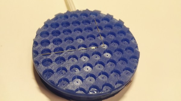
Desiccant is common in 3D printing because the drier plastic filament is, the better it prints. Beads of silica gel are great for controlling humidity, but finding a porous container for them that is a convenient size is a little harder. 3D printing is a generally useful solution for custom containers, but suffers from a slight drawback in this case: printing dense grills or hole patterns is not very efficient for filament-based printers. Dense hole patterns means lots of stopping and starting for the extruder, which means a lot of filament retractions and longer print times in general.

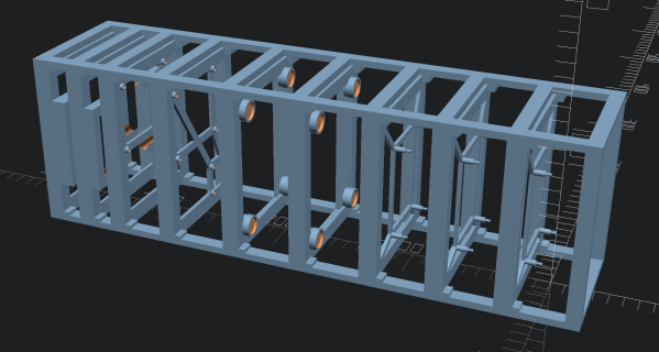
The green model is used as a modifier to the orange container (of which only the corners are left visible here)

[The_Redcoat]’s solution to this is to avoid hole patterns or grills altogether, and instead print large wall sections of the container as infill-only, with no perimeter layers at all. The exposed infill pattern is dense enough to prevent small beads of desiccant from falling through, while allowing ample airflow at the same time. The big advantage here is that infill patterns are also quite efficient for the printer to lay down. Instead of the loads of stops and starts and retractions needed to print a network of holes, infill patterns are mostly extruded in layers of unbroken lines. This translates to faster print speeds and an overall more reliable outcome, even on printers that might not be as well tuned or calibrated as they could be.

To get this result, [The_Redcoat] modeled a normal, flat-walled container then used OpenSCAD to create a stack of segments to use as a modifier in PrusaSlicer. The container is printed as normal, except where it intersects with the modifier, in which case those areas get printed with infill only and no walls. The result is what you see here: enough airflow for the desiccant to do its job, while not allowing any of the beads to escape. It’s a clever use of both a high infill as well as the ability to use a 3D model as a slicing modifier.

There’s also another approach to avoiding having to print a dense pattern of holes, though it is for light-duty applications only: embedding a material like tulle into a 3D print, for example, can make a pretty great fan filter.

Guide To Mastering OpenSCAD Costs Roughly The Same As OpenSCAD

OpenSCAD is a fantastic free tool for 3D modeling, but it’s far less intuitive to use for non-programmers than mouse-driven programs such as Tinkercad. Powerful as it may be, the learning curve is pretty steep. OpenSCAD’s own clickable cheat sheet and manual comes in handy all the time, but those are really more of a reference than anything else. Never fear, because [Jochen Kerdels] had quite the productive lockdown and wrote a free comprehensive guide to mastering OpenSCAD.

[Jochen]’s book opens with a nice introduction to OpenSCAD and it’s user environment and quickly moves into 10 useful projects of increasing complexity that start with simple stuff like wall anchors and shelf brackets and ends with recursive trees.

There are plenty of printing tips along the way to help realize these projects with minimum frustration, and the book wraps up by covering extra functions not expressly used in the projects.

Of course, you could always support [Jochen]’s Herculean effort by buying the print edition and forcing yourself to type everything in instead of copy/pasting, or give it to someone to introduce them to all the program has to offer.

Need help mastering OpenSCAD workflow? We’ve got that. Just want to make some boxes or airfoils? We have those in stock, too.

Main and thumbnail images via [Devlin Thyne]