Billiard Ball Finds A New Home In Custom Trackball Mouse

They walk among us, unseen by polite society. They seem ordinary enough on the outside but they hide a dark secret – sitting beside their keyboards are trackballs instead of mice. We know, it’s hard to believe, but that’s the wacky world we live in these days.

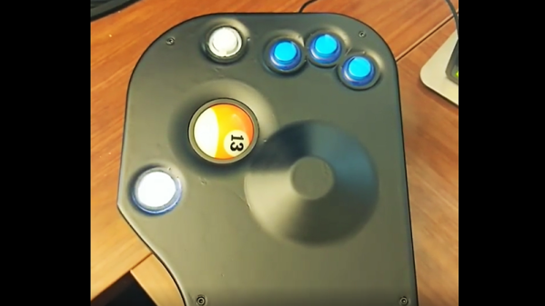
But we here at Hackaday don’t judge based on alternate input lifestyles, and we quite like this billiard ball trackball mouse. A trackball aficionado, [Adam Haile] spotted a billiard ball trackball in a movie and couldn’t resist the urge to make one of his own, but better. He was hoping for a drop-in solution using an off-the-shelf trackball, but alas, finding one with the needed features that fit a standard American 2-1/4″ (57.3 mm) billiard ball. Besides, he’s in the thumb control camp, and most trackballs that even come close to fitting a billiard ball are designed to be fiddled with the fingers.

So he started from the ground up – almost. A 1980s arcade-style trackball – think Centipede or Missile Command – made reinventing the trackball mechanism unnecessary, and was already billiard ball compatible. [Adam] 3D-printed a case that perfectly fit his hand, with the ball right under his thumb and arcade buttons poised directly below his fingers. A palm swell rises up to position the hand naturally and give it support. The case, which contains a Teensy to translate the encoder signals into USB commands, is a bit on the large side, but that’s to be expected for a trackball.

Still curious about how the other half lives? We’ve got plenty of trackball hacks for you, from the military to the game controller embedded to the strangely organic looking.

Seeing A Webcam’s PCBs In A Whole Different Light

When it comes to inspection of printed circuits, most of us rely on the Mark I eyeball to see how we did with the soldering iron or reflow oven. And even when we need the help of some kind of microscope, our inspections are still firmly in the visible part of the electromagnetic spectrum. Pushing the frequency up a few orders of magnitude and inspecting PCBs with X-rays is a thing, though, and can reveal so much more than what the eye can see.

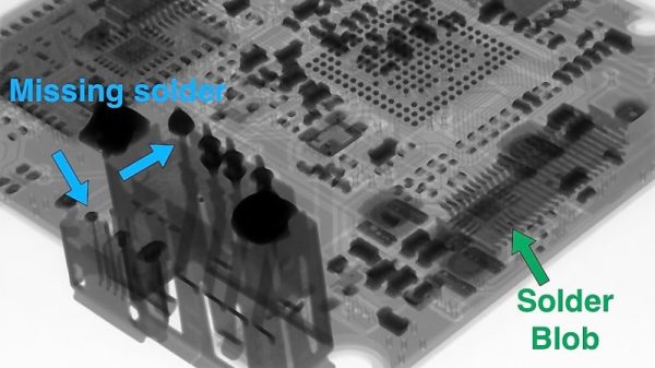
Unlike most of us, [Tom Anderson] has access to X-ray inspection equipment in the course of his business, so it seemed natural to do an X-ray enhanced teardown and PCB inspection. The victim for this exercise was nothing special – just a cheap WiFi camera of the kind that seems intent on reporting back to China on a regular basis. The guts are pretty much what you’d expect: a processor board, a board for the camera, and an accessory board for a microphone and IR LEDs. In the optical part of the spectrum they look pretty decent, with just some extra flux and a few solder blobs left behind. But under X-ray, the same board showed more serious problems, like vias and through-holes with insufficient solder. Such defects would be difficult to pick up in optical inspection, and it’s fascinating to see the internal structure of both the board and the components, especially the BGA chips.

If you’re stuck doing your inspections the old-fashioned way, fear not – we have tips aplenty for optical inspection. But don’t let that stop you from trying X-ray inspection; start with this tiny DIY X-ray tube and work your way up from there.

Thanks for the tip, [Jarrett].

Camera Uses Algorithms Instead Of Lenses

A normal camera uses a lens to bend light so that it hits a sensor. A pinhole camera doesn’t have a lens, but the tiny hole serves the same function. Now two researchers from the University of Utah. have used software to recreate images from scattered unfocused light. The quality isn’t great, but there’s no lens — not even a pinhole — involved. You can see a video, below.

The camera has a sensor on the edge of a piece of a transparent window. The images could resolve .1 line-pairs/mm at a distance of 150 mm and had a depth of field of about 10 mm. This may seem like a solution that needs a problem, but think about the applications where a camera could see through a windshield or a pair of glasses without having a conventional camera in the way.

Continue reading “Camera Uses Algorithms Instead Of Lenses”

Motorized Stage Finesses The Microscopic World

No matter how fine your fine motor skills may be, it’s really hard to manipulate anything on the stage of a microscope with any kind of accuracy. One jitter or caffeine-induced tremor means the feature of interest on the sample you’re looking at shoots off out of the field of view, and getting back to where you were is a tedious matter of trial and error.

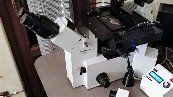
Mechanical help on the microscope stage is nice, and electromechanical help is even better, but a DIY fully motorized microscope stage with complete motion control is the way to go for the serious microscopist on a budget. Granted, not too many people are in [fabiorinaldus]’ position of having a swell microscope like the Olympus IX50, and those that do probably work for an outfit that can afford all the bells and whistles. But this home-brew stage ticks off all the boxes on design and execution. The slide is moved across the stage in two dimensions with small NEMA-8 steppers and microstepping controllers connected to two linear drives that are almost completely 3D-printed. The final resolution on the drives is an insane 0.000027344 mm. An Arduino lives in the custom-built control box and a control pad with joystick, buttons, and an OLED display allow the stage to return to set positions of interest. It’s really quite a build.

We’ve featured a lot of microscope hacks before, most of them concerning the reflective inspection scopes we all seem to covet for SMD work. But that doesn’t mean we haven’t shown love for optical scopes before, and electron microscopes have popped up a time or two as well.

Continue reading “Motorized Stage Finesses The Microscopic World”

First Light: The Story Of The Laser

Lasers are such a fundamental piece of technology today that we hardly notice them. So cheap that they can be given away as toys and so versatile that they make everything from DVD players to corneal surgery a reality, lasers are one of the building blocks of the modern world. Yet lasers were once the exclusive province of physicists, laboring over expansive and expensive experimental setups that seemed more the stuff of science fiction than workhouse tool of communications and so many other fields. The laser has been wildly successful, and the story of its development is an intriguing tale of observation, perseverance, and the importance of keeping good notes.

Continue reading “First Light: The Story Of The Laser”

Arduino And Encoder Form Precision Jig For Cutting And Drilling

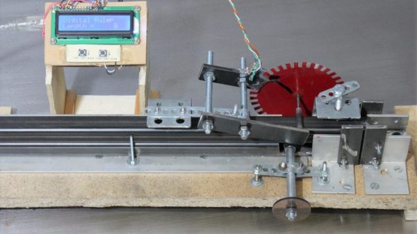
“Measure twice, cut once” is great advice in every aspect of fabrication, but perhaps nowhere is it more important than when building a CNC machine. When precision is the name of the game, you need measuring tools that will give you repeatable results and preferably won’t cost a fortune. That’s the idea behind this Arduino-based measuring jig for fabricating parts for a CNC build.

When it comes to building on the cheap, nobody holds a candle to [HomoFaciens]. We’ve seen his garbage can CNC build and encoders from e-waste and tin cans, all of which gave surprisingly good results despite incorporating such compliant materials as particle board and scraps of plumber’s strapping. Looking to build a more robust machine, he finds himself in need of parts of consistent and accurate lengths, so he built this jig. A sled of particle board and a fence of angle aluminum position the square tube stock, and a roller with a paper encoder wheel bears on the tube under spring pressure. By counting pulses from the optical sensors, he’s able to precisely position the tube in the jig for cutting and drilling operations. See it in action in the video after the break.

If you’ve been following [HomoFaciens], you’ll no doubt see where he’s been going — build a low-end tool, use that to build a better one, and so on. We’re excited to see him moving into more robust materials, but we’ll miss the cardboard and paperclip builds.

Continue reading “Arduino And Encoder Form Precision Jig For Cutting And Drilling”

Apollo: The Alignment Optical Telescope

The Apollo program is a constant reminder that we just don’t need so much to get the job done. Sure it’s easier with today’s tools, but hard work can do it too. [Bill Hammack] elaborates on one such piece of engineering: The Alignment Optical Telescope.

The telescope was used to find the position of the Lunar Module in space so that its guidance computer could do the calculations needed to bring the module home. It does this using techniques that we’ve been using for centuries on land and still use today in space; although now it’s done with computer vision. It was used to align the craft to the stars. NASA used stars as the fixed reference points for the coordinate system used to locate objects in space. But how was this accomplished with great precision?

The alignment optical telescope did this by measuring two unknowns needed by the guidance computer. The astronaut would find the first value by pointing the telescope in the general area necessary to establish a reading, then rotate the first reticle (a horizontal line) on the telescope until it touched the correct star. A ring assembly was then adjusted, moving an Archimedes spiral etched onto the viewfinder. When the spiral touches the star you can read the second value, established by how far the ring has been rotated.

If you’ve ever seen the Lunar Module in person, your first impression might be to giggle a bit at how crude it is. The truth is that much of that crudeness was hard fought to achieve. They needed the simplest, lightest, and most reliable assembly the world had ever constructed. As [Bill Hammack] states at the end of the video, breaking the complicated tool usually used into two simple dials is an amazing engineering achievement.

Continue reading “Apollo: The Alignment Optical Telescope”