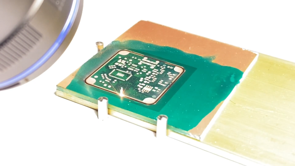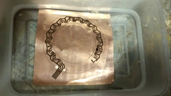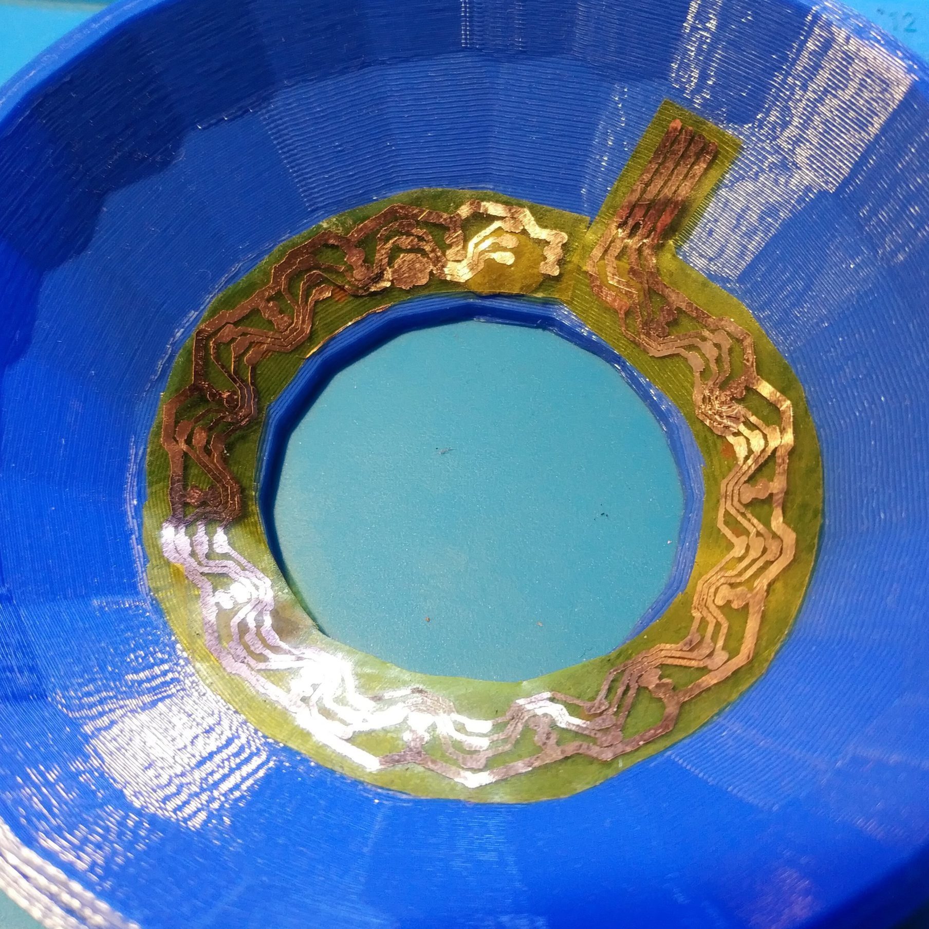
Creating your own PC board is a rite of passage for many. These days, though, you can order super inexpensive boards and have them in very little time, so it doesn’t always make sense to build your own. Still, some people like the challenge, and others don’t want to wait even a few days. Probably everyone has dreamed of a 3D printer-like machine that would just crank out beautiful PCBs. The Voltera V-One isn’t quite at that level of sophistication, but it isn’t too far from it. [Great Scott] shows us how he built two different boards using the system in the video below. While the results were impressive, you can also see that there are several limitations, especially if you are not designing your board with the machine in mind.
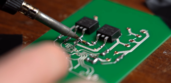
One thing that is obvious is that the machine does need your help. In addition to aligning holes, you’ll need to install tiny rivets for vias and slightly less tiny rivets for through-hole components. The last time we looked at the machine, it didn’t do holes at all, but [Scott] shows the drill attachment which allows the machine to produce vias and support leaded components.
Continue reading “Hands On With The Voltera V-One PCB Printer”