Anyone who has done an electronic engineering qualification will at some point have had to get to grips with transmission lines, and then if they are really lucky, waveguides. Perhaps there should be one of those immutable Laws stating that for each step in learning about these essential parts, the level of the maths you are expected to learn goes up in an exponential curve, for it’s certainly true that most of us breathe a hefty sigh of relief when that particular course ends. It’s not impossible to understand waveguides though, and [Old Hack EE] is here to slice through the formulae with some straightforward explanations.
First of all we learn about the basics of propagation in a waveguide, then we look at the effects of dimension on frequency. Again, there’s little in the way of head-hurting maths, just real-world explanations of cutt-off frequencies, and of coupling techniques. For the first time we’ve seen, here are simple and understandable explanations of the different types of splitter, followed up by the famous Magic T. It’s all in the phase, this is exactly the stuff we wish we’d had at university.
The world needs more of this type of explanation, after all it’s rare to watch a YouTube video and gain an understanding of something once badly taught. Take a look, the video is below the break.
Continue reading “The Waveguide Explanation You Wish You’d Had At School”

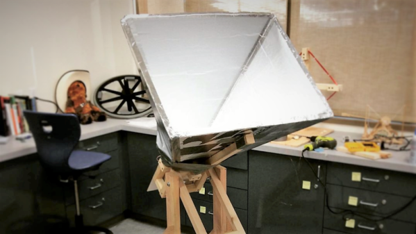
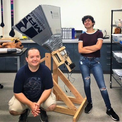 But to do any of this, you need a receiver, and that starts with a horn antenna to collect the weak signal. In collaboration with a former student, high school teacher [ArtichokeHeartAttack] built a pyramidal horn antenna of insulation board and foil tape. This collects RF signals and directs them to the waveguide, built from a rectangular paint thinner can with a quarter-wavelength stub antenna protruding into it. The signal from the antenna is then piped into an inexpensive