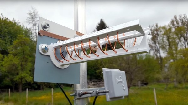
Super 8 Camera Brought Back To Life

The Super 8 camera, while a groundbreaking video recorder in its time, is borderline unusable now. Even if you can get film for it (and afford its often enormous price), it still only records on 8mm film which isn’t exactly the best quality of film around, not to mention that a good percentage of these cameras couldn’t even record audio. They were largely made obsolete by camcorders in the late ’80s and early ’90s, although some are still used for niche artistic purposes. If you’d rather not foot the bill for the film, though, you can still put one of these to work with the help of a Raspberry Pi.

[befinitiv] has a knack for repurposing antique analog equipment like this while preserving its aesthetic. While the bulk of the space inside of this camera would normally be used for housing film, this makes a perfect spot to place a Raspberry Pi Zero, a rechargeable battery, and a power converter circuit all in a 3D printed enclosure that snaps into the camera just as a film roll would have. It uses the Pi camera module but still makes use of the camera’s built in optics which include a zoom function. [befinitiv] also incorporated the original record button so that from the outside this looks like a completely unmodified Super 8 camera.

The camera can connect to a WiFi network and can stream live video to a computer, or it can record video files to an internal SD card. As a bonus, thanks to the power converter circuit, it is also capable of charging a cell phone. [befinitiv] notes that many of the aesthetic properties of 8 mm film seem to be preserved when using this method, and he has several theories as to why but no definitive answer. If you’d like to take a look at some of his other projects like this, check out this analog camera that is now able to take digital pictures. Continue reading “Super 8 Camera Brought Back To Life”

Extracting The WiFi Firmware And Putting Back A Keylogger

In the interest of simplification or abstraction, we like to think of the laptop on the kitchen table as a single discrete unit of processing. In fact, there is a surprisingly large number of small processors alongside the many cores that make up the processor. [8051enthusiast] dove into the Realtek rtl8821ae WiFi chip on his laptop and extracted the firmware. The Realtek rtl8821ae chip is a fairly standard Realtek chip as seen in this unboxing (which is where the main image comes from).

True to his name, [8051enthusiast] was pleased to find that the rtl8821ae was clearly based on the Intel 8051. The firmware was loaded on startup from a known file path and loaded onto the chip sitting in an M.2 slot. Careful consideration, [8051enthusiast] reasoned that the firmware was using RTX51 Tiny, which is a small real-time kernel.

The firmware is loaded at 0x4000 but it calls to code below that address, which means there is a ROM on the chip that contains some code. The easiest way to extract it would be to write some custom code that just copies the masked ROM back to the main CPU via the shared memory-mapped config space, but the firmware is checksummed by the masked ROM code. However, the checksum is just a 16-bit XOR. With a tweak in the kernel to allow accessing the shared config space from userspace, [8051enthusiast] was on his way to a complete firmware image.

Next, [8051enthusiast] looked at what could be done with his newfound hackability. The keyboard matrix is read by the Embedded Controller (EC), which happens to be another 8051 based microcontroller. There also happens to be an RX and a TX trace from the EC to the m.2 slot (where the rtl8821ae is). This has to do with 0x80 postcodes from the processor being routed out somewhere accessible via the EC. With a bit of custom code on both the EC and the WiFi chip, [8051enthusiast] had a keylogger that didn’t run on the main processor broadcasting the PS/2 keystrokes as UDP packets.

Of course, there are plenty of other 8051 based devices out there just waiting to be discovered. Like this 8051 based e-ink display controller.

[Main image source: Realtek RTL8821AE unboxing on YouTube by Евгений Горохов]

Bringing The Game Boy Camera Into The 21st Century

The Game Boy Camera is probably one of the most limited-specification digital cameras to have been mass-marketed, yet it occupies a special position in the hearts of many because despite being a toy with a paltry 128×128 monochrome sensor it was for many the first camera they owned. [Matt Grey] was among those people, and was always frustrated by the device’s inability to export pictures except to the Game Boy printer. So after having bodged together an interface a decade ago but not being happy with it, he returned to the project and made a wireless carrier for the camera that allows easy transfer through WiFi to his mobile phone.

Inside the slab-like 3D-printed enclosure lies a GBxCart RW Game Boy cartridge reader, whose USB port is wired to a Raspberry Pi Zero on which are a set of scripts to read the camera and make its photos available for download via a web browser. At last the camera is a stand-alone unit, allowing the easy snapping and retrieval of as many tiny black and white images as he likes. There’s a video showing the device in action, which we’ve placed for your enjoyment below the break.

This camera has appeared in so many projects on these pages over the years, but we’re guessing that the work on whose shoulders this one stands would be the moment its workings were reverse engineered.

Continue reading “Bringing The Game Boy Camera Into The 21st Century”

WiFi Penetration Testing With An ESP32

WiFi is one of those technologies that most of us would have trouble living without. Unfortunately, there are several vulnerabilities in the underlying 802.11 standards that could potentially be exploited. To demonstrate just how simple this can be, [risinek] developed the ESP32 Wi-Fi Penetration Tool that runs on cheap dev boards and can execute deauthentication and Denial of Service attacks, and capture handshakes and PMKIDs.

The main challenge in this project is to implement these attacks while using the ESP-IDF development framework. The closed source WiFi libraries of the ESP-IDF block specific arbitrary frames like deauthentication frames. To get around this [risinek] used two different approaches. The first is to bypass the declaration of the blocking function at compile-time, which is borrowed from the esp32-deauther project. The second approach doesn’t require any modifications to the ESP-IDF. It works by creating a rogue access point (AP) identical to the targeted access point, which will send a deauthentication frame whenever one of the devices tries to connect to it instead of the real AP.

WPA/WPA2 handshakes are captured by passively listening for devices connecting to the target network, or running a deauth attack and then listening for when devices reconnect. PMKIDs are captured from APs with the roaming feature enabled, by analyzing the first message of a WPA handshake. ESP32 Wi-Fi Penetration Tool will also format the captured data into PCAP and HCCAPX files ready to be used with Wireshark and Hashcat. To manage the tool, it creates a management access point where the target and attack type is selected, and the resulting data can be downloaded. Pair the ESP32 with a battery, and everything can be done on the go. The project is part of [risinek]’s master’s thesis, and the full academic article is an educating read. Continue reading “WiFi Penetration Testing With An ESP32”

New Part Day: ESP32-WROOM-DA

We’re always interested in the latest from the world’s semiconductor industry here at Hackaday, but you might be forgiven for noticing something a little familiar about today’s offering from Espressif. The ESP32-WROOM-DA has more than a passing resemblance to the ESP32-WROOM dual-core-microcontroller-with-WiFi  module that we’ve seen on so many projects over the last few years because it’s a WROOM, but this one comes with a nifty trick to deliver better WiFi connectivity.

The clever WiFi trick comes in the form of a pair of antennas at 90 degrees to each other. It’s a miniaturised version of the arrangement with which you might be familiar from home routers, allowing the device to select whichever antenna gives the best signal at any one time.

We can see that the larger antenna footprint will require some thought in PCB design, but otherwise the module has the same pinout as the existing WROVER. It’s not much of a stretch to imagine it nestled in the corner of a board at 45 degrees, and we’re sure that we’ll see it appearing in projects directly. Anything that enhances the connectivity of what has become the go-to wireless microcontroller on these pages can only be a good thing.

DIY Wireless Serial Adapter Speaks (True) RS-232

There is a gotcha lurking in wait for hackers who look at a piece of equipment, see a port labeled “Serial / RS-232”, and start to get ideas. The issue is the fact that the older the equipment, the more likely it is to be a bit old-fashioned about how it expects to speak RS-232. Vintage electronics may expect the serial data to be at bipolar voltage levels that are higher than what the typical microcontroller is used to slinging, and that was the situation [g3gg0] faced with some vintage benchtop equipment. Rather than deal with cables and wired adapters, [g3gg0] decided to design a wireless adapter with WiFi and Bluetooth on one end, and true RS-232 on the other.

The adapter features an ESP32 and is attached to a DB-9 plug, so it’s nice and small. It uses the ST3232 chip to communicate at 3 V logic levels on the microcontroller side, supports bipolar logic up to +/-13 V on the vintage hardware side, and a rudimentary web interface allows setting hardware parameters like baud rate. The nice thing about the ST3232 transceiver is that it is not only small, but can work from a 3 V supply with only four 0.1 uF capacitors needed for the internal charge pumps.

As for actually using the adapter, [g3gg0] says that the adapter’s serial port is exposed over TCP on port 23 (Telnet) which is supported by some programs and hardware. Alternately, one can connect an ESP32 to one’s computer over USB, and run firmware that bridges any serial data directly to the adapter on the other end.

Design files including schematic, bill of materials, and PCB design are shared online, and you can see a brief tour of the adapter in the video, embedded below.

Continue reading “DIY Wireless Serial Adapter Speaks (True) RS-232”

New Part Day: Espressif ESP32-C6 Includes WiFi 6 And A RISC-V Core

If you’re a reader of Hackaday, then you’ve almost certainly encountered an Espressif part. The twin microcontroller families ESP8266 and ESP32 burst onto the scene and immediately became the budget-friendly microcontroller option for projects of all types. We’ve seen the line expand recently with the ESP32-C3 (packing a hacker-friendly RISC-V core) and ESP32-S3 with oodles of IO and fresh new CPU peripherals. Now we have a first peek at the ESP32-C6; a brand new RISC-V based design with the hottest Wi-Fi standard on the block; Wi-Fi 6.

There’s not much to go on here besides the standard Espressif block diagram and a press release, so we’ll tease out what detail we can. From the diagram it looks like the standard set of interfaces will be on offer; they even go so far as to say “ESP32-C6 is similar to ESP32-C3” so we’ll refer you to [Jenny’s] excellent coverage of that part. In terms of other radios the ESP32-C6 continues Espressif’s trend of supporting Bluetooth 5.0. Of note is that this part includes both the coded and 2 Mbps Bluetooth PHYs, allowing for either dramatically longer range or a doubling of speed. Again, this isn’t the first ESP32 to support these features but we always appreciate when a manufacturer goes above and beyond the minimum spec.

Welcome to the ESP32-C6

The headline feature is, of course, Wi-Fi 6 (AKA 802.11ax). Unfortunately this is still exclusively a 2.4GHz part, so if you’re looking for 5GHz support (or 6GHz in Wi-Fi 6E) this isn’t the part for you. And while Wi-Fi 6 brings a bevy of features from significantly higher speed to better support for mesh networks, that isn’t the focus here either. Espressif have brought a set of IoT-centric features; two radio improvements with OFDMA and MU-MIMO, and the protocol feature Target Wake Time.

OFDMA and MU-MIMO are both different ways of allowing multiple connected device to communicate with an access point simultaneously. OFDMA allows devices to slice up and share channels more efficiency; allowing the AP more flexibility in allocating its constrained wireless resources. With OFDMA the access point can elect to give an entire channel to a single device, or slice it up to multiplex between more than once device simultaneously. MU-MIMO works similarly, but with entire antennas. Single User MIMO (SU-MIMO) allows an AP and connected device to communicate using a more than one antenna each. In contrast Multi User MIMO (MU-MIMO) allows APs and devices to share antenna arrays between multiple devices simultaneously, grouped directionally.

Finally there’s Target Wake Time, the simplest of the bunch. It works very similarly to the Bluetooth Low Energy (4.X and 5.X) concept of a connection interval, allowing devices to negotiate when they’re next going to communicate. This allows devices more focused on power than throughput to negotiate long intervals between which they can shut down their wireless radios (or more of the processor) to extended battery life.

These wireless features are useful on their own, but there is another potential benefit. Some fancy new wireless modes are only available on a network if every connected device supports them. A Wi-Fi 6 network with 10 Wi-Fi 6 devices and one W-Fi 5 (802.11ac) one may not be able to use all the bells and whistles, degrading the entire network to the lowest common denominator. The recent multiplication of low cost IoT devices has meant a corresponding proliferation of bargain-basement wireless radios (often Espressif parts!). Including new Wi-Fi 6 exclusive features in what’s sure to be an accessible part is a good start to alleviating problems with our already strained home networks.

When will we start seeing the ESP32-C6 in the wild? We’re still waiting to hear but we’ll let you know as soon as we can get our hands on some development hardware to try out.

Thanks to friend of the Hackaday [Fred Temperton] for spotting this while it was fresh!