search-console

Fooling Google Search Console With Tricky PHP

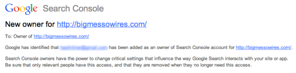
When [Steve] received a notice from Google that a new owner had been added to his Google Search Console account, he knew something was wrong. He hadn’t added anyone to his account. At first he thought it might be a clever phishing tactic. Maybe the email was trying to get him to click a malicious link. Upon further investigation, he discovered that it was legitimate. Some strange email address had been added to his account. How did this happen?

When you want to add a website to Google’s services, they require that you prove that you own the actual website as a security precaution. One method to provide proof is by uploading or creating an HTML file to your website with some specific text inside. In this case, the file needed to be called “google1a74e5bf969ded17.html” and it needed to contain the string “google-site-verification: googlea174e5bf969ded17.html”.

[Steve] logged into his web server and looked in the website directory but he couldn’t find the verification file. Out of curiosity, he tried visiting the web page anyways and was surprised to find that it worked. After some experimentation, [Steve] learned that if he tried to load any web page that looked like “googleNNNNNNN.html”, he would be presented with the corresponding verification code of “google-site-verification: googleNNNNNNNN.html”. Something was automatically generating these pages.

After further investigation, [Steve] found that some malicious PHP code had been added to his website’s index.php page. Unfortunately the code was obfuscated, so he couldn’t determine exactly what was happening. After removing the new code from the index.php file, [Steve] was able to remove the hacker’s email address from [Steve’s] Google account.

This is a very interesting hack, because not only did it allow this one hacker to add himself to [Steve’s] Google account, but it would also have allowed anyone else to do the same thing. This is because each new hacker would have been able to fool Google’s servers into thinking that they had uploaded the verification file thanks to the malicious PHP code. It makes us think that perhaps Google’s verification system should use a separate randomized string inside of the verification file. Perhaps one that can’t be guessed or calculated based on known variables such as the file name.

Transmitting MIDI Signals With XBEE

What do you do when you want to rock out on your keytar without the constraints of cables and wires? You make your own wireless keytar of course! In order to get the job done, [kr1st0f] built a logic translator circuit. This allows him to transmit MIDI signals directly from a MIDI keyboard to a remote system using XBEE.

[kr1st0f] started with a MIDI keyboard that had the old style MIDI interface with a 5 pin DIN connector. Many new keyboards only have a USB interface, and that would have complicated things. The main circuit uses an optoisolator and a logic converter to get the job done. The MIDI signals are converted from the standard 5V logic to 3.3V in order to work with the XBEE.

The XBEE itself also needed to be configured in order for this circuit to work properly. MIDI signals operate at a rate of 31,250 bits per second. The XBEE, on the other hand, works by default at 9,600 bps. [kr1st0f] first had to reconfigure the XBEE to run at the MIDI bit rate. He did this by connecting to the XBEE over a Serial interface and using a series of AT commands. He also had to configure proper ID numbers into the XBEE modules. When all is said and done, his new transmitter circuit can transmit the MIDI signals wirelessly to a receiver circuit which is hooked up to a computer.

How To Make Amazon Echo Control Fake WeMo Devices

[Chris] has been playing with the Amazon Echo. It’s sort of like having Siri or Google Now available as part of your home, but with built-in support for certain other home automation appliances like those from Belkin WeMo and Philips. The problem was [Chris] didn’t want to be limited to only those brands. He had other home automation gear that he felt should work with Amazon Echo, but didn’t. That’s when he came up with the clever idea to just emulate one of the supported platforms.

The WeMo devices use UPnP to perform certain functions over the network. [Chris] wanted to see how these communications actually worked, so he fired up his laptop and put his WiFi adapter into monitor mode. Then he used Wireshark to start collecting packets. He found that the device detection function starts out with the Echo searching for WeMo devices using UPnP. The device then responds to the Echo with the device’s URL using HTTP over UDP. The Echo then requests the device’s description using that HTTP URL. The description is then returned as an HTTP response.

The actual “on/off” functionality of the WeMo devices is simpler since the Echo already knows about the device. The Echo simply connects to the WeMo over the HTTP interface and issues a “SetBinaryState” command. The WeMo then obliges and returns a confirmation via HTTP.

WeMo Echo
How Echo Communicates with WeMo Devices

[Steve] was able to use this information to set up his own WeMo “virtual cloud”. Each virtual device would have its own IP address. They would also need to have a listener for UDP broadcasts as well as an HTTP listener running on the WeMo port 49153. Each virtual device would also need to be able to respond to the UPnP discovery requests and the “on/off” commands.

[Chris] used a Linux server, creating a new virtual Ethernet interface for each virtual WeMo switch. A single Python script runs the WeMo emulation, listening for the UPnP broadcast and sending a different response for each virtual device. Part of the response includes the device’s “friendly name”, which is what the Echo listens for when the user says voice commands. Since the virtual WeMo devices are free, this allows [Chris] to make multiple phrases for each device. So rather than be limited to “television”, he can also make a separate device for “TV” that performs the same function. [Chris] is also no longer limited to only specific brands of home automation gear.

There’s still a long way to go in hacking this device. There’s a lot of hardware under the hood to work with. Has anyone else gotten their hands (and bench tools) on one of these?

Combining Musical Hatred With Target Practice

Not everyone can agree on what good music is, but in some cases you’ll find that just about everyone can agree on what is awful. That’s what the people over at Neo-Pangea discovered when they were listening to Internet radio. When one of those terrible songs hits their collective eardrums, the group’s rage increases and they just need to skip the track.

This is how Engineers act if the song is super-awful

Rather than use a web app or simple push button to do the trick, they turned the “skip” button into a NERF target. They call their creation the Boom Box Blaster and made a fantastic demo film video about it which is found after the break.

Inspired by a painting in the office, the target takes the form of a small hot air balloon. The target obviously needed some kind of sensor that can detect when it is hit by a NERF dart. The group tried several different sensor types, but eventually settled on a medium vibration sensor. This sensor is connected to an Arduino, which then communicates with a Raspberry Pi over a Serial connection. The Pi uses a Python script to monitor the Arduino’s vibration sensor. The system also includes some orange LEDs to simulate flames and a servo attached to the string which suspends the balloon from the ceiling. Whenever a hit is registered, the flames light up and the balloon raises into the air to indicate that the shot was on target.

Continue reading “Combining Musical Hatred With Target Practice”

Using A TeensyLC To Emulate The XBOX 360 Controller

After the release of Mortal Kombat X, [Zachery’s] gaming group wanted to branch out into the fighter genre. They quickly learned that in order to maximize their experience, they would need a better controller than a standard gamepad. A keyboard wasn’t going to cut it either. They wanted a fight stick. These are large controllers that look very much like arcade fighting controls and include a joystick and large buttons. [Zachery’s] group decided to build their own fight stick for use with a PC.

[Zachery] based his build around the TeensyLC, which is a 32 bit development board with an ARM processor. It’s also compatible with Arduino. The original version of his project setup the controller as a HID, essentially emulating a keyboard. This worked for a while until they ran into compatibility issues with some games. [Zachery] learned that his controller was compatible with DirectInput, which has been deprecated. The new thing is Xinput, and it was going to require more work.

Using Xinput meant that [Zachery] could no longer use the generic Microsoft HID driver. Rather than write his own drivers, he decided to emulate the XBOX 360 controller. When the fight stick is plugged into the computer, it shows up as an XBOX 360 controller and Windows easily installs the pre-built driver. To perform the emulation, [Zachery] first had to set the VID and PID of the device to be identical to the XBOX controller. This is what allows the Microsoft driver to recognize the device.

Next, the device descriptor and configuration descriptor had to be added to the Teensy’s firmware. The device descriptor includes information such as USB version, device class, protocol, etc. The configuration descriptor includes additional information about the device configuration. [Zachery] used Microsoft Message Analyzer to pull the configuration descriptor from a real XBOX 360 controller, then used the same data in his own custom controller.

[Zachery] programmed the TeensyLC using the Arduino IDE. He ran into some trouble here because the IDE did not include the correct device type for an Xinput device. [Zachery] had to edit the boards.txt file and add three lines of code in order to add a new hardware device to the IDE’s menu. Several other files also had to be modified to make sure the compiler knew what an Xinput device type was.  With all of that out of the way, [Zachery] was finally able to write the code for his controller.

Electric Go Kart has More Features than a Tesla

Making Mario Kart Real

If you’ve ever had a casual go-kart experience, you might be able to relate to [HowToLou]. He noticed that whenever he tried to race, the same situation inevitably always happened. One racer would end up in front of the pack, and no one else would be able to pass them. The result was more of a caravan of go-karts than an actual race. That’s when he realized that video games like Mario Kart had already figured out how to fix this problem long ago. [Lou] took ideas from these games and implemented them onto a real life go-kart in order to improve the experience. The result is what he calls a Flash Kart.

The key to improving the experience was to add more features that you don’t normally get in a real word go-karting experience. The Flash Kart uses an electronic drive system that is controlled by computer. This setup allows the computer to limit the speed of the kart so they are all the same. The system includes a Logitech gaming steering wheel with built-in control buttons. There is also a color LCD screen mounted as a heads up display. The screen displays the racer’s speed in miles per hour, as well as multiple MP3 music tracks to choose from. The system provides the user with a limited number of speed boost tokens, listed on the heads up display. The user can also view their current ranking, their location on the track, or even get a view directly behind them.

The back of the kart includes a 23″ LCD screen that shows other players who you are and what team you are on. For added fun, the rider can display taunting messages to other racers using this screen. The front of the kart includes a laser cannon for shooting other karts as well as a “token scoop” sensor. This allows the riders to pick up virtual items such as laser cannon ammo, shields, or extra speed boost tokens.

To pack in all of this added functionality, [Lou] started with a typical go-kart chassis. From there, he built a custom fiber glass shell for the back-end. This houses most of the sensitive electronics. The system is powered by three 12V deep cycle batteries. A 15HP electric motor drives the rear wheels. The throttle is controlled with a gas pedal that simply feeds to a sensor that is hooked up to the control computer. The heart of the system is a computer that runs on a 2.6Ghz small footprint Zotac motherboard with Windows XP. The software is custom written in C#. The computer is plugged into a miniLAB 1008 interface board. This is how it communicates with all of the various sensors. The interface board is also used to control a number of relays which in turn control the speed of the kart.

Unfortunately [Lou] built this kart years ago and doesn’t include many details about what sensors he is using, or how the software works. Still, this was such a cool idea that we had to share it. Be sure to watch [Lou’s] video below to see the kart in action. Continue reading “Making Mario Kart Real”

Camera Light Meter

Upgrading An Old Camera With A New Light Meter

[Marc] has an old Voigtländer Vito CLR film camera. The camera originally came with an analog light meter built-in. The meter consisted of a type of solar panel hooked up to a coil and a needle. As more light reached the solar panel, the coil became energized more and more, which moved the needle farther and farther. It was a simple way of doing things, but it has a down side. The photo panels stop working over time. That’s why [Marc] decided to build a custom light meter using newer technology.

[Marc] had to work within the confines of the tiny space inside of the camera. He chose to use a LM3914 bar display driver IC as the primary component. This chip can sense an input voltage against a reference voltage and then display the result by illuminating a single LED from a row of ten LEDs.

[Marc] used a photo cell from an old calculator to detect the ambient light. This acts as a current source, but he needed a voltage source. He designed a transimpedence amplifier into his circuit to convert the current into a voltage. The circuit is powered with two 3V coil cell batteries, regulated to 5V. The 5V acts as his reference voltage for the display driver. With that in mind, [Marc] had to amplify this signal further.

It didn’t end there, though. [Marc] discovered that when sampling natural light, the system worked as intended. When he sampled light from incandescent light bulbs, he did not get the expected output. This turned out to be caused by the fact that incandescent lights flicker at a rate of 50/60 Hz. His sensor was picking this up and the sinusoidal output was causing problems in his circuit. He remedied this by adding two filtering capacitors.

The whole circuit fits on a tiny PCB that slides right into position where the original light meter used to be. It’s impressive how perfectly it fits considering everything that is happening in this circuit.

[Thanks Mojay]