Fail Of The Week: 3D Printed Worm Gear Drive Project Unveils Invisible Flaw

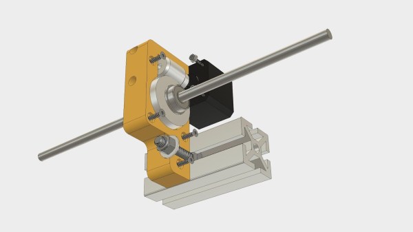
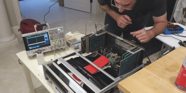
All of us would love to bring our projects to life while spending less money doing so. Sometimes our bargain hunting pays off, sometimes not. Many of us would just shrug at a failure and move on, but that is not [Mark Rehorst]’s style. He tried to build a Z-axis drive for his 3D printer around an inexpensive worm gear from AliExpress. This project was doomed by a gear flaw invisible to the human eye, but he documented the experience so we could all follow along.

We’ve featured [Mark]’s projects for his ever-evolving printer before, because we love reading his well-documented upgrade adventures. He’s not shy about exploring ideas that run against 3D printer conventions, from using belts to drive the Z-axis to moving print cooling fan off the print head (with followup). And lucky for us, he’s not shy about document his failures alongside the successes.

He walks us through the project, starting from initial motivation, moving on to parts selection, and describes how he designed his gearbox parts to work around weaknesses inherent to 3D printing. After the gearbox was installed, the resulting print came out flawed. 
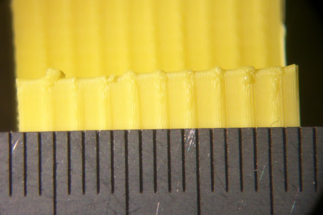
Each of the regularly spaced print bulge can be directly correlated to a single turn of the worm gear making it the prime suspect. Then, to verify this observation more rigorously, Z-axis movement was measured with an indicator and plotted against desired movement. If the problem was caused by a piece of debris or surface damage, that would create a sharp bump in the plot. The sinusoidal plot tells us the problem is more fundamental than that.

This particular worm gear provided enough lifting power to move the print bed by multiplying motor torque, but it also multiplied flaws rendering it unsuitable for precisely positioning a 3D printer’s Z-axis. [Mark] plans to revisit the idea when he could find a source for better worm gears, and when he does we’ll certainly have the chance to read what happens.

Scratch-Built Ornithopter: Here’s How I Flapped My Way To Flight

One of humankind’s dreams has always been to fly like a bird. For a hacker, an achievable step along the path to that dream is to make an ornithopter — a machine which flies by flapping its wings. An RC controlled one would be wonderful, controlled flight is what everyone wants. Building a flying machine from scratch is a big enough challenge, and a better jumping-off point is to make a rubber band driven one first.

I experimented with designs which are available on the internet, to learn as much as possible, but I started from scratch in terms of material selection and dimensions. You learn a lot about flight through trial and error, and I’m happy to report that in the end I achieved a great little flyer built with a hobby knife and my own two hands. Since then I’ve been looking back on what made that project work, and it’s turned into a great article for Hackaday. Let’s dig in!

Continue reading “Scratch-Built Ornithopter: Here’s How I Flapped My Way To Flight”

Stylish Business Card With A Stylophone Built In

If you’re in the electronics business, PCB business cards seem like a natural fit. They may be impractical and expensive, but they can really set you apart from that boring paper card from Vistaprint crowd. But they need to make sense for what you do, so for a musician and MIDI pro, this MIDI-controller stylophone business card is a real eye- and ear-catcher.

This business card is an idea that [Mitxela] has been kicking around for a while, and he even built a prototype a couple of years ago. The homebrew card, made using the spray paint, laser etching, and ferric chloride method, worked well enough as a proof of concept, but it was a little rough around the edges and needed the professional touch of a PCB fabricator. We’ve got to say that the finished cards are pretty darn sexy, with the black resist contrasting nicely against the gold-immersion pads. He selected a 1-mm thick board and made the USB connector as a separate small board; snapped off of the main board and reflowed back on, it builds up the edge connector to the proper thickness. The parts count is low — just an ATtiny85 and a resistor ladder to encode each key, with a simple jumper used as the stylus. The device itself is just a MIDI controller and makes no music on its own, but we still think this is a pretty creative way to hang out a shingle.

[Mitxela] has quite a few interesting builds, and is no stranger to our pages. Check out his recent servo-plucked MIDI music box, or these amazing miniature LED earrings.

Continue reading “Stylish Business Card With A Stylophone Built In”

Antique Lighthouse Lens Via CNC

Before the invention of the high-powered LED, and even really before the widespread adoption of electric lights in general, lighthouses still had the obligation of warning ships of dangers while guiding them into various safe harbors. They did this with gas lights and impressive glass lenses known as Fresnel lenses which helped point all available light in the correct direction while reducing weight and material that would otherwise be used in a conventional lens.

Now, a company in Florida is using acrylic in reproductions of antique Fresnel lenses. At first glance, it seems like acrylic might not be the best substitute for glass, but the company is able to achieve extreme precision using a CNC machine and then polishing and baking the acrylic which makes it transparent and excellent for use in lighthouse lenses like this. The reproduction lenses are built out of brass, and the lens elements are glued in place with a special adhesive. It’s a convincing replication worthy of use in any lighthouse.

Be sure to check out the video below to see how these lenses are built, and although we’re not entirely sure what exactly is being sprayed on the lenses when they are being polished, perhaps someone in the comments section can illuminate that for us. Of course, there are other uses for Fresnel lenses than in lighthouses, and we’ve seen some great examples of them put to use for many different applications.

Continue reading “Antique Lighthouse Lens Via CNC”

Soundproofing A CNC Mill Conversion

The Proxxon MF70 is a nice desktop sized milling machine with a lot of useful add-on accessories available for it, making it very desirable for a hacker to have one in his or her home workshop. But its 20000 rpm spindle can cause quite the racket and invite red-faced neighbors. Also, how do you use a milling machine in your home-workshop without covering the whole area in metal chips and sawdust? To solve these issues, [Tim Lebacq] is working on Soundproofing his CNC mill conversion.

To meet his soundproof goal, he obviously had to first convert the manual MF70 to a CNC version. This is fairly straightforward and has been done on this, and similar machines, in many different ways over the years. [Tim] stuck with using the tried-and-tested controller solution consisting of a Raspberry Pi, an Arduino Uno and a grbl shield sandwich, with stepper motor drivers for the three NEMA17 motors. The electronics are housed inside the reclaimed metal box of an old power supply. Since the Proxxon MF70 is already designed to accept a CNC conversion package, mounting the motors and limit switches is pretty straightforward making it easy for [Tim] to make the upgrade.

Soundproofing the box is where he faced unknown territory. The box itself is made from wooden frames lined with particle board. A pair of drawer slides with bolt-action locks is used for the front door which opens vertically up. He’s also thrown in some RGB strips controlled via the Raspberry-Pi for ambient lighting and status indications. But making it soundproof had him experimenting with various materials and techniques. Eventually, he settled on a lining of foam sheets topped up with a layer of — “bubble wrap” ! It seems the uneven surface of the bubble wrap is quite effective in reducing sound – at least to his ears. Time, and neighbours, will tell.

Maybe high density “acoustic foam” sheets would be more effective (the ones similar to “egg crate” style foam sheets, only more dense)? Cleaning the inside of the box could be a big challenge when using such acoustic foam, though. What would be your choice of material for building such a sound proof box? Let us know in the comments below. Going back many years, we’ve posted about this “Portable CNC Mill” and a “Mill to CNC Conversion” for the Proxxon MF70. Seems like a popular machine among hackers.

Diablo Drive Appears To Be Cursed

[CuriousMarc] didn’t think it would be a big deal when a former Xerox employee sent him an Alto Diablo drive for service. Turns out the drive was cursed — it would destroy everything it touched including a set of heads and an alignment cartridge. [Marc] and a partner spent two months trying to get the drive operable and the video of their process is pretty interesting.

We were interested in the troubleshooting, but we were really envious of their lab, full of HP workstations, an IBM mainframe, and even a Selectric. We kept having to rewind the video because we had tuned out while we were staring at some of the equipment in the background.

The guys got a lot of practice aligning the heads on the drive. Because the crashed head was bent, it actually dug into the alignment cartridge so on subsequent attempts they had to manually load the disk past the damage. They learned to leave the disk a little out of alignment because tightening the assembly will move it a little bit. If you were already aligned, the heads would be off after you did the tightening.

They used a custom FPGA-based tester that [Carl] developed after reverse engineering the disk format. It is amazing to watch the big drive in action and realize that a standard cartridge for this machine was 2.5 megabytes. There was another controller and disk system called the Trident that would get you a whopping 80 megabytes, but we don’t think this is one of those.

Did they succeed in exorcising whatever demons lived in the drive? Watch the video and find out. Even if you never have to fix a Diablo drive yourself, you’ll be entertained. Especially when they work out how to do a current adjustment on the drive by simulating the circuit in Spice.

We’ve seen a lot about the Alto which is surprising considering how few of them were built. We’ve seen a restoration and even an odd use for a light bulb related to the Alto’s CRT.

Continue reading “Diablo Drive Appears To Be Cursed”

GPS synchronized Nixie tube clock from kit

3D Printed Tool Tips To Straighten DIP Chips And Unstraighten Resistors

Watching someone assemble a kit is a great way to see some tools you may have not encountered before and maybe learn some new tricks. During [Marco Reps’] recent build of a GPS synchronized Nixie clock kit we spied a couple of handy tools that you can 3D print for your own bench.

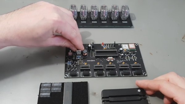
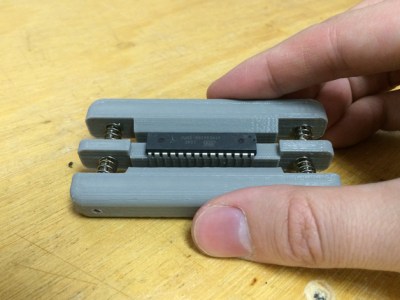
Fresh from the factory Dual Inline Package (DIP) chips come with their legs splayed every so slightly apart — enough to not fit into the carefully designed footprints on a circuit board. You may be used to imprecisely bending them by hand on the surface of the bench. [Marco] is more refined and shows off a neat little spring loaded tool that just takes a couple of squeezes to neatly bend both sides of the DIP, leaving every leg the perfect angle. Shown here is a 3D printed version called the IC Pin Straightener that you can throw together with springs and common fasteners.

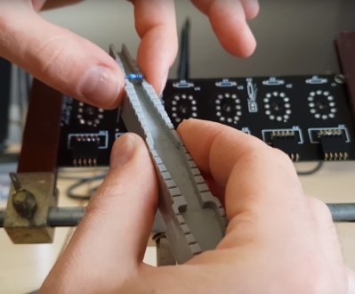
Another tool which caught our eye is the one he uses for bending the metal film resistor leads: the “Biegelehre” or lead bending tool. You can see that [Marco’s] tool has an angled trench to account for different resistor body widths, with stepped edges for standard PCB footprint spacing. We bet you frequently use the same resistor bodies so 3D printing is made easier by using a single tool for each width. If you really must copy what [Marco] is using, we did find this other model that more closely resembles his.

As for new tricks, there are a lot of small details worth appreciating in the kit assembly. [Marco] cleans up the boards using snips to cut away the support material and runs them over sandpaper on a flat surface. Not all Nixie tubes are perfectly uniform so there’s some manual adjustment there. And in general his soldering practices are among the best we’ve seen. As usual, there’s plenty of [Marco’s] unique brand of humor to enjoy along the way.

We have a warm spot in our heart for simple tools you can whip up on the ‘ole 3D printer. Check out the PCB vise, a set of ball and socket helping hands, and a collection of toolbag essentials.

Continue reading “3D Printed Tool Tips To Straighten DIP Chips And Unstraighten Resistors”