If you look up at the night sky in a dark enough place, with enough patience you’re almost sure to see a satellite cross the sky. It’s pretty cool to think you’re watching light reflect off a hunk of metal zipping around the Earth fast enough to never hit it. Unfortunately, it doesn’t work during the daylight hours, and you really only get to see satellites in low orbits.
Thankfully, there’s a trick that allows you to see satellites any time of day, even the ones in geosynchronous orbits — you just need to look using microwaves. That’s what [Gabe] at [saveitforparts] did with a repurposed portable satellite dish, the kind that people who really don’t like being without their satellite TV programming when they’re away from home buy and quickly sell when they realize that toting a satellite dish around is both expensive and embarrassing. They can be had for a song, and contain pretty much everything needed for satellite comms in one package: a small dish on a motorized altazimuth mount, a low-noise block amplifier (LNB), and a single-board computer that exposes a Linux shell.
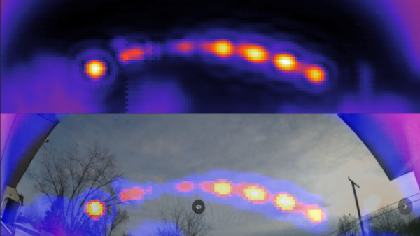
After figuring out how to command the dish to specific coordinates and read the signal strength of the received transponder signals, [Gabe] was able to cobble together a Python program to automate the task. The data from these sweeps of the sky resulted in heat maps that showed a clear arc of geosynchronous satellites across the southern sky. It’s quite similar to something that [Justin] from Thought Emporium did a while back, albeit in a much more compact and portable package. The video below has full details.
[Gabe] also tried turning the dish away from the satellites and seeing what his house looks like bathed in microwaves reflected from the satellite constellation, which worked surprisingly well — well enough that we’ll be trawling the secondary market for one of these dishes; they look like a ton of fun.
Continue reading “See Satellites In Broad Daylight With This Sky-Mapping Dish Antenna” →