A 3D Printed Micro:Bit Nunchuk

As [Paul Bardini] explains on the Thingiverse page for his “Micro:Bit Hand Controller”, the Bluetooth radio baked into the BBC’s educational microcontroller makes it an ideal choice for remotely controlling things. You just need to give it a nice enclosure, a joystick, a couple of buttons, and away you go. You can even use the integrated accelerometer as another axis of control. This is starting to sound a bit familiar, especially to gamers.

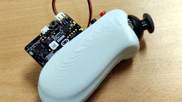
While it might not come with the Official Nintendo Seal of Quality, the 3D printable enclosure [Paul] has come up with for the Micro:Bit certainly takes more than a little inspiration from the iconic Wii “Nunchuck” controller. He’s jostled around the positions of the joystick and momentary buttons a bit, but it still has that iconic one-handed ergonomic styling.

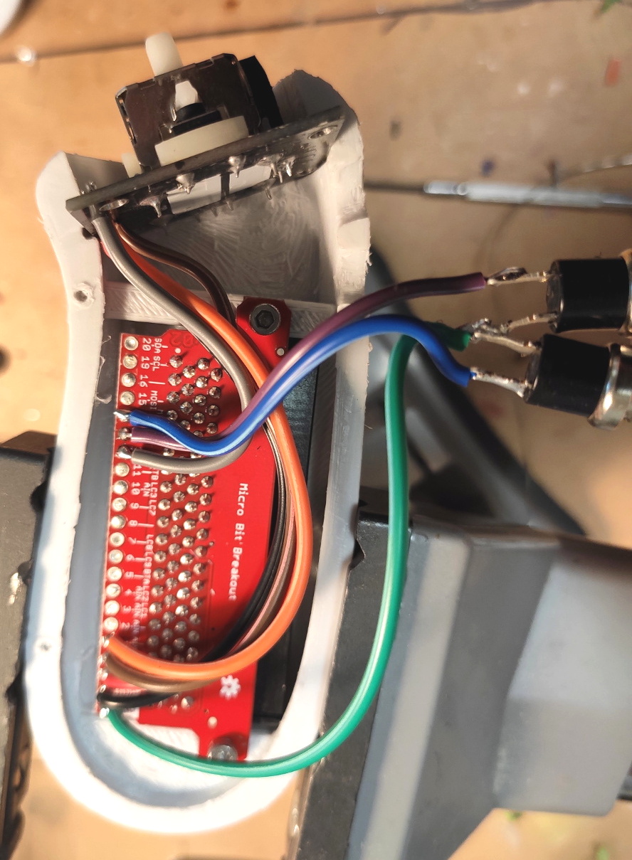
In a particularly nice touch, [Paul] has built his controller around a Micro:Bit breakout board from SparkFun that allows you to plug the microcontroller in via its edge connector. This means you can pull the board out and still use it in other projects. The only other connection to the controller leads to the battery, which uses a two pin JST-PH plug that can easily be removed.

Thanks to this breakout board, the internal wiring is exceptionally simple. The joystick (the type used in a PS2 controller) and the buttons are simply soldered directly to pins on the breakout board. No passives required, just a few short lengths of flexible wiring to snake through the printed enclosure.

The Thingiverse page only has the STLs for the two halves of the controller, and no source code for the Micro:Bit itself. But it shouldn’t be terribly hard to piece together the basic functionality with example code that’s floating around out there. Especially since you can run Python on them now. Of course, you could also add Bluetooth to the original Wii version if you’re not looking to reinvent the wheel nunchuck.

Teardown: VeriFone MX 925CTLS Payment Terminal

Regular Hackaday readers may recall that a little less than a year ago, I had the opportunity to explore a shuttered Toys “R” Us before the new owners gutted the building. Despite playing host to the customary fixture liquidation sale that takes place during the last death throes of such an establishment, this particular location was notable because of how much stuff was left behind. It was now the responsibility of the new owners to deal with all the detritus of a failed retail giant, from the security camera DVRs and point of sale systems to the boxes of employee medical records tucked away in a back office.

Clipping from New York Post. September 24th, 2018.

The resulting article and accompanying YouTube video were quite popular, and the revelation that employee information including copies of social security cards and driver’s licenses were left behind even secured Hackaday and yours truly a mention in the New York Post. As a result of the media attention, it was revealed that the management teams of several other stores were similarly derelict in their duty to properly dispose of Toys “R” Us equipment and documents.

Ironically, I too have been somewhat derelict in my duty to the good readers of Hackaday. I liberated several carloads worth of equipment from Geoffrey’s fallen castle with every intention of doing a series of teardowns on them, but it’s been nine months and I’ve got nothing to show for it. You could have a baby in that amount of time. Which, incidentally, I did. Perhaps that accounts for the reshuffling of priorities, but I don’t want to make excuses. You deserve better than that.

So without further ado, I present the first piece of hardware from my Toys “R” Us expedition: the VeriFone MX 925CTLS. This is a fairly modern payment terminal with all the bells and whistles you’d expect, such as support for NFC and EMV chip cards. There’s a good chance that you’ve seen one of these, or at least something very similar, while checking out at a retail chain. So if you’ve ever wondered what’s inside that machine that was swallowing up your debit card, let’s find out.

Continue reading “Teardown: VeriFone MX 925CTLS Payment Terminal”

A Guide To Shop Equipment Nobody Thinks About: Clean, Organized, And Efficient

When planning out a workspace at home, the job, or at a makerspace, we all tend to focus on the fun parts. Where the equipment will go, how you’ll power it, what kind of lights you’ll get, etc, etc. It’s easy to devote all your attention to these high-level concepts, which often means the little details end up getting addressed on the fly. If they get addressed at all.

But whether we want to admit it or not, an organized workspace tends to be more efficient. That’s why [Eric Weinhoffer] has put together a blog post that details all those mundane details that we tend to forget about. It’s not exactly exciting stuff, and contains precisely as much discussion about whiteboards as you probably expect. That said, it’s thorough and clearly comes from folks who’ve had more than a little experience with setting up an efficient shop.

So what’s the first thing most shops don’t have enough of? Labels. [Eric] says you should put labels on everything, parts bins, tools, machines, if it’s something you need to keep track of, then stick a label on it. This does mean you’ll likely have to buy a label maker, but hey, at least that means a new gadget to play with.

Of course, those self-stick labels don’t work on everything. That’s why [Eric] always has a few rolls of masking tape (such as the blue 3M tape you might be using on your 3D printer bed) and some quality markers on hand to make arbitrary labels. Apparently there’s even such a thing as dry erase tape, which lets you throw an impromptu writing surface anywhere you want.

[Eric] also suggests investing in some collapsible cardboard bins which can be broken down and stored flat when not in use. If you’ve got the kind of situation where you’ll always have more or less the same amount of stuff then plastic is probably your best bet, but in a more dynamic environment, being able to collapse the bins when they aren’t in use is a capability we never even realized we needed until now.

As you might imagine, the post also touches on the issues of keeping sufficient safety gear available. We’ve talked about this in the past, but it’s one of those things that really can’t be said too many times. Having a wall of meticulously labeled storage bins is great, but it’s going to be the last thing on your mind if you manage to get an eye full of superglue.

Phase Shift Pump Control? There’s An App For That.

The sort of pumps used in the filtration systems of fountains and swimming pools don’t take kindly to running dry. So putting such a pump on a simple timer to run while you’re away comes with a certain level of risk: if the pump runs out of water while you’re gone, you might come home to a melted mess. One possible solution is a float sensor to detect the water level in whatever you’re trying to pump, but that can get complicated when you’re talking about something as large as a pool.

For his entry into the 2019 Hackaday Prize, [Luc Brun] is working on controller that can detect when the pump is running dry by monitoring the phase shift between voltage and current. With an inductive load like a pump, the current should lag behind the AC voltage a bit under normal operation. But if they become too far out of phase with each other, that’s a sign that the pump is running in a no-load condition because there’s no water to slow it down.

As [Luc] explains in the project write-up, simply monitoring the pump’s peak current could work, but it would be less reliable. The problem is that different motors have different current consumptions, so unless you calibrated the controller to the specific load it’s protecting, you could get false readings. But the relationship between current and voltage should remain fairly consistent between different motors.

The controller is powered by a Arduino Nano and uses a ACS712 current sensor to take phase measurements. Since he had the ability to toggle the pump on and off with a relay attached to the Arduino, [Luc] decided to add in a few other features. The addition of a DS1307 Real Time Clock means the pump can be run on a schedule, and an HC-05 Bluetooth module lets him monitor the whole system from his smartphone with an Android application he developed.

Since the theme of this year’s Hackaday Prize is designing a product rather than a one-off build, judges will be looking for exactly the sort of forward thinking that [Luc] has demonstrated here. As the controller is currently a mass of individual modules held inside a waterproof enclosure, the next steps for this project will likely be the finalization of the hardware design and the production of a custom PCB.

An Arduino Sickbay Display Worthy Of The Enterprise

The various displays and interfaces in Star Trek, especially The Original Series, were intentionally designed to be obtuse and overly complex so they would appear futuristic to the audience. If you can figure out how Sulu was able to fly the Enterprise with an array of unlabeled buttons and rocker switches, we’d love to hear it. But one area of the ship where this abstract design aesthetic was backed off a bit was sickbay, as presumably they wanted the audience to be able to understand at a glance whether or not Kirk or Spock were going to pull through their latest brush with death (spoilers: they’re fine).

For his latest project, [XTronical] has recreated the classic displays from Dr McCoy’s sickbay with an Arduino Nano and a 2.8 inch LCD display. It even has a speaker and MP3 player module to recreate the “heartbeat” sound from the original show. The whole thing looks and sounds phenomenal, and would be a perfect desk toy for the classic Trek aficionado. But this isn’t just a toy, it’s a fully functional medical scanner.

Of course, this little gadget can’t tell you if you’ve come down with a nasty case of Rigellian fever, but it can read your vitals using a MAX30100 pulse oximeter module and DS18B20 thermometer. In fact, it actually has two DS18B20 sensors: one to measure ambient temperature, the other to measure skin temperature. With those two figures, [XTronical] says it can calculate your core body temperature. The only thing that’s made up is the blinking “Respiration” indicator, that one’s just an estimate.

So where do we go from here? This project is presented as merely the first step in building a complete prop, perhaps in the form of a medical tricorder. We’ve seen some phenomenal TOS tricorder builds over the years, and some have even used the Raspberry Pi to shoehorn a bit of functionality into them. [XTronical] says he’s working on getting the source code and a step-by-step build guide put together, so keep an eye out for that in the near future.

Continue reading “An Arduino Sickbay Display Worthy Of The Enterprise”

Bringing FPGA Development To The Masses

The Field Programmable Gate Array (FPGA) is one of the most exciting tools in the modern hacker’s arsenal. If you can master the FPGA, you can create hardware devices that not only morph and change based on your current needs, but can power through repetitive tasks at phenomenal rates. The only problem is, working with FPGAs can be a bit intimidating for newbies. One could argue that the technology is waiting on its “Arduino” moment; the introduction of a cheap development board coupled with easy to use software that brings FPGA hacking into the mainstream.

If everything goes according to plan, the wait might soon be over. [Ryan Jacobs] believes his project WebFPGA is the easiest and fastest way to get your hands dirty with this incredible technology. Outwardly the hardware could pass for an Arduino Nano clone, with a bunch of GPIO pins and a couple of LEDs on a small breadboard-friendly PCB. Certainly a no-frills presentation. It’s the software side is where things get interesting: all you need to develop for this FPGA is a modern web browser.

Currently Chrome, Opera, and Edge are supported, even if they’re running on relatively low-end computers. [Ryan] says this makes it much easier and cheaper to roll out FPGA classes in schools, as students can do everything with their existing Chromebooks. As the video after the break shows, you can even get away with using a sufficiently powerful smartphone to do some FPGA hacking on the go.

So what’s the trick? Essentially the heavy-lifting is done remotely: all of the synthesis is performed in their cloud backend, with the final bitstream delivered to the user for installation through WebUSB. If you’re more comfortable on the command line, [Ryan] says they’re currently working on tools which will allow you to perform all the necessary interactions with their cloud service without the browser.

The more critical Hackaday reader will likely be concerned about lock-in. What happens if you buy one of these development boards without a license for the service, or worse, what happens if WebFPGA goes belly-up down the road? To that end, [Ryan] makes it clear that their hardware is completely compatible with existing offline FPGA development tools such as the open source IceStorm.

We’ve seen considerable interest in low-cost FPGA development platforms, with readers perhaps recalling the excitement surrounding the fire sale of the Pano Logic thin clients. Despite efforts to make developing for these systems even easier, it’s hard to imagine the bar getting much lower than what WebFPGA is shooting for. Their Kickstarter campaign is close to crossing the finish line, and we’re very interested to see where the product goes from here.

Continue reading “Bringing FPGA Development To The Masses”

Sprucing Up A Bell & Howell Model 34 Oscilloscope

We’ll admit it, in an era when you can get a four channel digital storage oscilloscope with protocol decoding for a few hundred bucks, it can be hard not to see the appeal of analog CRT scopes from decades past. Sure they’re heavy, harder to use, and less capable, but they just look so cool. Who could say no to having one of these classic pieces of gear on their bench?

[Cody Nybo] certainly couldn’t. Despite the fact that he already has a digital scope, he couldn’t pass up the chance to add a Bell & Howell Schools Model 34 from circa 1973 to his collection. It needed a bit of TLC before it could be brought back into service, but now it’s all fixed up and ready to put in some work. Not bad for a piece of gear with nearly a half-century on the clock.

The restoration of the Model 34 was aided by the fact that [Cody] got the original manual and schematics for the scope in the deal, which he was kind enough to scan and upload for the rest of the class to enjoy. Those of you who have worked on older electronics can already guess where the scope needed the most love: all the capacitors needed to be swapped out for fresh ones. He also found a few resistors that were out of spec, and the occasional bad solder joint here and there.

Even if you’re not looking to repair your own middle-aged oscilloscope, his pictures of the inside of Model 34 are fascinating. The scope was sold as a kit, so the construction is surprisingly simple and almost entirely point-to-point. Of course, there’s something of a trade-off at work: [Cody] says it won’t display much more than 2.5 MHz before things start getting wonky. But then again, that’s a more than reasonable frequency ceiling for audio work and most hobbyist projects.

Oscilloscopes have come a long way since the days when they had to draw out their readings on a piece of paper. While newer devices have all but buried the classic analog scope, a beauty like this would still have a place of honor in our lab.