A Work Of Art That Also Receives AM And SSB

Over the winter, [Michael LeBlanc] thought a good way to spend his time during those long dark nights would be to scratch build his own direct conversion receiver. He was able to find plans for such a project easily enough online, but where’s the fun in following instructions? The final result incorporates what he found online with his own unique tweaks and artistic style.

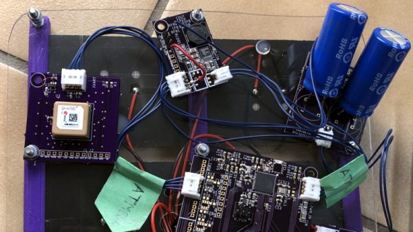
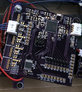
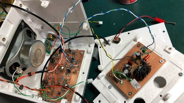
[Michael] based his receiver on a modified approach to the DC40 created by [Ashhar Farhan], a name likely familiar to readers involved in amatuer radio. He further modified the design by swapping out the audio amplifier for a TDA2003A, and bolted on a digital tuner by way of an Arduino and a Si5351 clock generator. There’s a small OLED to show the current frequency, which is adjusted with a high-quality Bourns EM14 optical encoder so he can surf the airwaves in the comfort and style.

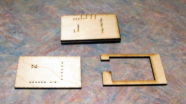
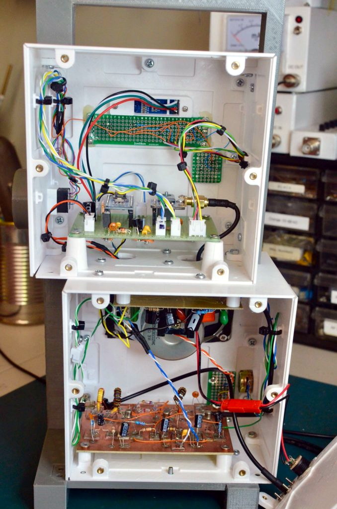
The digital tuner mated to the analog DC40 receiver gives the radio an interesting duality, which [Michael] really embraces with his enclosure design. From a practical standpoint he wanted to keep the two halves of the system in their own boxes to minimize any interference, but the 3D printed case exaggerates that practical consideration into a fascinating conversation piece.

The analog and digital compartments are askew, and their rotary controls are on opposite sides. The radio looks like it might topple over if it wasn’t for the fact that the whole thing is bolted together, complete with brass inserts for the printed parts. The integrated carry handle at the top somehow manages to make it look vintage and ultra-modern at the same time. Rarely do you see a printed enclosure that’s both meticulously designed inside and aesthetically pleasing externally. [Michael] earned his 3D Printing Merit Badge for sure with this one.

Continue reading “A Work Of Art That Also Receives AM And SSB”

Laser Cutting Wooden Pogo Pin Test Jigs

Now as far as problems go, selling so many products on Tindie that you need to come up with a faster way to test them is a pretty good one to have. But it’s still a problem that needs solving. For [Eric Gunnerson] the solution involved finding a quick and easy way to produce wooden pogo test jigs on his laser cutter, and we have a feeling he’s not the only one who’ll benefit from it.

The first step was exporting the PCB design from KiCad into an SVG, which [Eric] then brought into Inkscape for editing. He deleted all of the traces that he wasn’t interested in, leaving behind just the ones he wanted to ultimately tap into with the pogo pins. He then used the Circle tool to put a 0.85 mm red dot in the center of each pad.

You’re probably wondering where those specific parameters came from. The color is easy enough to explain: his GlowForge laser cutter allows him to select by color, so [Eric] can easily tell the machine to cut out anything that’s red. As for the size, he did a test run on a scrap of wood and found that 0.85 mm was the perfect dimensions to hold onto a pogo pin with friction.

[Eric] ran off three identical pieces of birch plywood, plus one spacer. The pogo pins are inserted into the first piece, the wires get soldered around the back, and finally secured with the spacer. The whole thing is then capped off with the two remaining pieces, and wrapped up in tape to keep it together.

Whether you 3D print one of your own design or even modify a popular development board to do your bidding, the test jig is invaluable when you make the leap to small scale production.

A Solar-Powered Box Of Sensors To Last 100 Years

It’s a simple goal: build a waterproof box full of environmental sensors that can run continuously for the next century. OK, so maybe it’s not exactly “simple”. But whatever you want to call this epic quest to study and record the planet we call home, [sciencedude1990] has decided to make his mission part of the 2019 Hackaday Prize.

The end goal might be pretty lofty, but we think you’ll agree that the implementation keeps the complexity down to a minimum. Which is important if these solar-powered sensor nodes are to have any chance of going the distance. A number of design decisions have been made with longevity in mind, such as replacing lithium ion batteries that are only good for a few hundred recharge cycles with supercapacitors which should add a handful of zeros to that number.

At the most basic level, each node in the system consists of photovoltaic panels, the supercapacitors, and a “motherboard” based on the ATmega256RFR2. This single-chip solution provides not only an AVR microcontroller with ample processing power for the task at hand, but an integrated 2.4 GHz radio for uploading data to a local base station. [sciencedude1990] has added a LSM303 accelerometer and magnetometer to the board, but the real functionality comes from external “accessory” boards.

Along the side of the main board there’s a row of ports for external sensors, each connected to the ATmega through a UART multiplexer. To help control energy consumption, each external sensor has its own dedicated load switch; the firmware doesn’t power up the external sensors until they’re needed, and even then, only if there’s enough power in the supercapacitors to do so safely. Right now [sciencedude1990] only has a GPS module designed to plug into the main board, but we’re very interested in seeing what else he (and perhaps even the community) comes up with.

The Future Of Space Is Tiny

While recent commercial competition has dropped the cost of reaching orbit to a point that many would have deemed impossible just a decade ago, it’s still incredibly expensive. We’ve moved on from the days where space was solely the domain of world superpowers into an era where multi-billion dollar companies can join on on the fun, but the technological leaps required to reduce it much further are still largely relegated to the drawing board. For the time being, thing’s are as good as they’re going to get.

Starlink satellites ready for launch

If we can’t count on the per pound cost of an orbital launch to keep dropping over the next few years, the next best option would logically be to design spacecraft that are smaller and lighter. Thankfully, that part is fairly easy. The smartphone revolution means we can already pack an incredible amount sensors and processing power into something that can fit in the palm of your hand. But there’s a catch: the Tsiolkovsky rocket equation.

Often referred to as simply the “rocket equation”, it allows you to calculate (among other things) the ratio of a vehicle’s useful cargo to its total mass. For an orbital rocket, this figure is very small. Even with a modern launcher like the Falcon 9, the payload makes up less than 5% of the liftoff weight. In other words, the laws of physics demand that orbital rockets are huge.

Unfortunately, the cost of operating such a rocket doesn’t scale with how much mass it’s carrying. No matter how light the payload is, SpaceX is going to want around $60,000,000 USD to launch the Falcon 9. But what if you packed it full of dozens, or even hundreds, of smaller satellites? If they all belong to the same operator, then it’s an extremely cost-effective way to fly. On the other hand, if all those “passengers” belong to different groups that split the cost of the launch, each individual operator could be looking at a hundredfold price reduction.

SpaceX has already packed 60 of their small and light Starlink satellites into a single launch, but even those craft are massive compared to what other groups are working on. We’re seeing the dawn of a new era of spacecraft that are even smaller than CubeSats. These tiny spacecraft offer exciting new possibilities, but also introduce unique engineering challenges.

Continue reading “The Future Of Space Is Tiny”

Failed Scooter Proves The Worth Of Modular Design

Like many mechanically inclined parents, [Tony Goacher] prefers building over buying. So when his son wanted an electric scooter, his first stop wasn’t to the toy store, but to AliExpress for a 48V hub motor kit. Little did he know that the journey to getting that scooter road-ready would be a bit more involved than he originally bargained for.

She cannae take anymore, Captain

Of course, to build a motorized scooter you need a scooter to begin with. So in addition to the imported motor, [Tony] picked up a cheap kick scooter on eBay. Rather than worrying about the intricacies of cleanly integrating the two halves of the equation, he decided to build a stand-alone module that contained all of the electronics. To attach it to the scooter, he’d cut off the rear wheel and literally bolt his module to the deck.

[Tony] goes into considerable detail on how he designed and manufactured his power unit, from prototyping with laser cut MDF to the final assembly of the aluminum parts that he produced on a CNC of his own design. It’s really a fantastic look at how to go from idea to functional device, with all the highs and lows in between. When the first attempt at mounting the battery ended up cutting into the 8 Ah LiPo pack for example, and treated his son to a bit of a light show.

With all the bugs worked out and his son happily motoring around the neighborhood, [Tony] thought his job was done. Unfortunately, it was not to be. It turned out that his bolt-on power unit had so much kick that it sheared the front wheel right off. Realizing the little fellow didn’t have the fortitude for such electrified exploits, he went to a local shop and got a much better (and naturally much more expensive) donor for the project.

It’s here that his modular approach to the problem really paid off. Rather than having to redesign a whole new motor mount for the different scooter, he just lopped the back wheel off and bolted it on just as he did with the cheapo model. What could easily have been a ground-up redesign turned out to be a few minutes worth of work. Ultimately he did end up machining a new front axle for the scooter so he could fit a better wheel, but that’s another story.

Scooters would seem to be the unofficial vehicle of hackers, as we’ve seen a long line of hacked up two-wheeled rides over the years. From relatively low-key modifications of thrift store finds, to street-legal engineering marvels. We’ve even seen scooters fitted with trailers, so even the tiniest of proto-hackers can come along for the ride.

Continue reading “Failed Scooter Proves The Worth Of Modular Design”

Ditch The Switch: A Soft Latching Circuit Roundup

For some of us, there are few sounds more satisfying than the deep resonant “thunk” of a high quality toggle switch slamming into position. There isn’t an overabundance of visceral experiences when working with electronics, so we like to savor them when we get the chance. But of course there’s no accounting for taste, and we suppose there are even situations where a heavy physical switch might not be the best solution. So what do you do?

Enter the latching power circuit, often referred to as a “soft” switch. [Chris Chimienti] has recently put together a fascinating video which walks the viewer through five different circuits which can be used to add one of these so-called soft power switches to your project. Each circuit is explained, diagramed, annotated, and eventually even demonstrated on a physical breadboard. The only thing you’ve got to do is pick which one you like the most.

There’s actually a number of very good reasons to abandon the classic toggle switch for one of these circuits. But the biggest one, somewhat counterintuitively, is cost. Even “cheap” toggle switches are likely to be one of the most expensive components in your bill of materials, especially at low volume. By comparison, the couple of transistors and a handful of passive components it will take to build out one of these latching circuits will only cost you a couple of cents.

Even if you aren’t in the market for a new way to turn off your projects, this roundup of circuits is a fantastic reminder of how powerful discrete components can be. In an age where most projects seem assembled from pre-fabbed modules, it’s occasionally refreshing to get back to basics.

Continue reading “Ditch The Switch: A Soft Latching Circuit Roundup”

The Practical Approach To Keeping Your Laser In Focus

You could be forgiven for thinking that laser cutters and engravers are purely two dimensional affairs. After all, when compared to something like your average desktop 3D printer, most don’t have much in the way of a Z axis: the head moves around at a fixed height over the workpiece. It’s not as if they need a leadscrew to push the photons down to the surface.

But it’s actually a bit more complicated than that. As [Martin Raynsford] explains in a recent post on his blog, getting peak performance out of your laser cutter requires the same sort of careful adjustment of the Z axis that you’d expect with a 3D printer. Unfortunately, the development of automated methods for adjusting this critical variable on lasers hasn’t benefited from the same kind of attention that’s been given to the problem on their three dimensional counterparts.

Ultimately, it’s a matter of focus. The laser is at its most powerful when its energy is concentrated into the smallest dot possible. That means there’s a “sweet spot” in front of the lens where cutting and engraving will be the most efficient; anything closer or farther away than that won’t be as effective. As an example, [Martin] says that distance is exactly 50.3 mm on his machine.

The problem comes when you start cutting materials of different thicknesses. Just a few extra millimeters between the laser and your target material can have a big difference on how well it cuts or engraves. So the trick is maintaining that perfect distance every time you fire up the laser. But how?

One way to automate this process is a touch probe, which works much the same as it does on a 3D printer. The probe is used to find where the top of the material is, and the ideal distance can be calculated from that point. But in his experience, [Martin] has found these systems leave something to be desired. Not only do they add unnecessary weight to the head of the laser, but the smoke residue that collects on the touch probe seems to invariably mar whatever surface you’re working on with its greasy taps.

In his experience, [Martin] says the best solution is actually the simplest. Just cut yourself a little height tool that’s precisely as long as your laser’s focal length. Before each job, stick the tool in between the laser head and the target to make sure you’re at the optimal height.

On entry level lasers, adjusting the Z height is likely to involve turning some screws by hand. But you can always add a motorized Z table to speed things up a bit. Of course, you’ll still need to make sure your X and Y alignment is correct. Luckily, [Martin] has some tips for that as well.