Quick And Dirty MIDI Interface With USBASP

[Robson Couto] recently found himself in need of MIDI interface for a project he was working on, but didn’t want to buy one just to use it once; we’ve all been there. Being the creative fellow that he is, he decided to come up with something that not only used the parts he had on-hand but could be completed in one afternoon. Truly a hacker after our own hearts.

Searching around online, he found documentation for using an ATtiny microcontroller as a MIDI interface using V-USB. He figured it shouldn’t be too difficult to adapt that project to run on one of the many USBASP programmers he had laying around, and got to work updating the code.

Originally written for the ATtiny2313, [Robson] first had to change around the pin configuration so it would work on the ATmega8 in the USBASP, and also updated the USB-V implementation to the latest version. With the code updated, he programmed one of the USBASP adapters with a second one by connecting them together and putting a jumper on the J2 header.

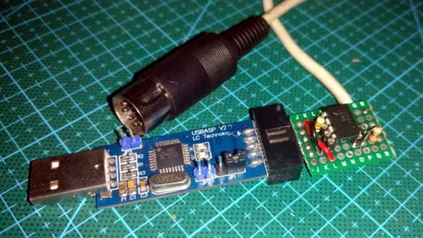
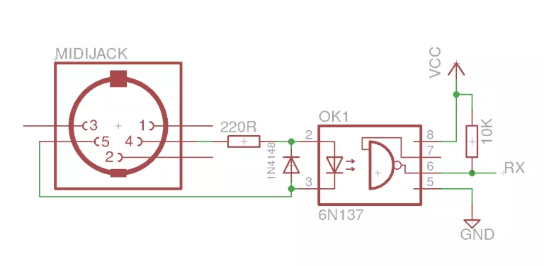
He had the software sorted, but there was still a bit of hardware work to do. To provide isolation for the MIDI device, he put together a small circuit utilizing a 6N137 optoisolator and a couple of passive components on a piece of perf board. It’s not pretty, but it does fit right into the programming connector on the USBASP. He could have fired up his PCB CNC but thought it was a bit overkill for such a simple board.

[Robson] notes that he hasn’t implemented MIDI output with his adapter, but that the code and the chip are perfectly capable of it if you need it for your project. Finding the schematic to hook up to the programmer’s TX pin is left as an exercise for the reader.

If you don’t have a USBASP in the parts bin, we’ve seen a very similar trick done with an Arduino clone in the past.

Launchpad MIDI Controller Put To Work With Python

For Hackaday readers who might not spend their free time spinning electronic beats at raves, the Launchpad by Novation is a popular peripheral for creating digital music with tools such as Ableton Live. It’s 8×8 grid of RGB LED backlit buttons are used to trigger different beats and clips by sending MIDI commands to the computer over USB. While not a strict requirement for performing digital music, it also helps that it looks like you’re flying a spaceship when using it.

It’s definitely a slick piece of gear, but the limited stock functionality means you’re unlikely to see one outside of the Beat Laboratory. Though that might change soon thanks to LPHK, created by [Ella Jameson]. She’s created a program in Python that allows you to use the Novation Launchpad as a general purpose input device. But rather than taking the easy way out by just turning the hardware into a USB HID device or something along those lines, LPHK implements an impressive set of features including its own internal scripting language.

In the video after the break, [Ella] walks us through some basic use cases, such as launching programs or controlling the system volume with individual buttons. LPKH has a GUI which provides a virtual representation of the Launchpad, and allows configuring each button’s color and function as well as saving and loading complete layouts.

For more advanced functionality, LPHK utilizes a scripting language that was inspired by the Hak5 USB Rubber Ducky. Scripts are written with plain English commands and very simple syntax, meaning you don’t need to have any programming experience to create your own functions. There’s also a script scheduling system with visual feedback right on the board: if a button is pulsing red it means it has a script waiting for its turn to execute. When the key is rapidly flashing the script is actively running. A second tap of the button will either remove it from the queue or kill the running script, depending on what the status was when you hit it.

[Ella] makes it clear this software is still a work in progress; it’s not as polished as she’d like and still has bugs, but it’s definitely functional for anyone who’s looking to wring a bit more functionality out of their $150 Launchpad. She’s actively looking for beta testers and feedback, so if you’ve already got one of these boards give it a shot and let her know what you think.

In the past we’ve seen hackers fiddling with the open source API Novation released for their Launchpad controllers, but overall there hasn’t been a lot of work done with these devices. Perhaps that will soon change with powerful software like this in development.

Continue reading “Launchpad MIDI Controller Put To Work With Python”

Arduino Nitrox Analyzer For The Submarine Hacker

For Hackaday readers who don’t spend their free time underwater, nitrox is a blend of nitrogen and oxygen that’s popular with scuba divers. Compared to atmospheric air, nitrox has a higher concentration of oxygen; which not only allows divers to spend more time underwater but also reduces the risk of decompression sickness. Of course when fiddling with the ratio of gases you breathe there’s a not inconsequential risk of dying, so nitrox diving requires special training and equipment to make sure the gas mixture is correct.

Divers can verify the ratio of oxygen to nitrogen in their nitrox tanks with a portable analyzer, though as you might expect, they aren’t exactly cheap. But if you’re confident in your own hacking skills, [Eunjae Im] might have the solution for divers looking to save some cash. He’s come up with an Arduino based nitrox analyzer that can be built for considerably less than the cost of a commercial unit.

Now before you get the torches lit up, we should be clear: ultimately the accuracy, and therefore safety, of this device depends on the quality of the oxygen sensor used. [Eunjae] isn’t suggesting you get a bottom of the barrel sensor for this build, and in fact links to a replacement sensor that’s intended for commercial nitrox analyzers as a way to verify the unit is up to the task. The downside is that the sensor alone runs $80. If you want to go with something cheaper, you do so at your own risk.

With a suitable sensor in hand, the project really boils down to building up an interface and enclosure for it. [Eunjae] is using an Arduino Nano, a 128×64 OLED screen, and a battery inside of a rugged waterproof case. He also added an ADS1115 16 Bit DAC between the oxygen sensor and the Arduino for fast and accurate readings over I2C. With the hardware assembled, calibrating the device is as simple as taking it outside and making sure you get an oxygen reading of 20.9% (the atmospheric normal).

While [Eunjae] is happy with his analyzer on the whole, he does see a few areas which could be improved in future revisions. The case is bulky and rather unattractive, something that could be addressed with a custom 3D printed case (though waterproofing it might be an issue). He also says the only reason he used a 9V alkaline battery was because he had it on hand, a small rechargeable battery pack would be a much more elegant solution.

We’ll go out on a limb and say that most Hackaday readers aren’t avid scuba divers. For better or for worse, we’re the sort of folks who stay in the shallow end of the pool. But when one of our ilk does dip below the waves, they really seem to go all out.

Continue reading “Arduino Nitrox Analyzer For The Submarine Hacker”

Revive That Old Analog Cell Phone With SDR

With the latest and greatest 5G cellular networks right around the corner, it can be difficult to believe that it wasn’t so long ago that cell phones relied on analog networks. They aren’t used anymore, but it might only take a visit to a swap meet or flea market to get your hands on some of this vintage hardware. Of course these phones of a bygone era aren’t just impractical due to their monstrous size compared to modern gear, but because analog cell networks have long since gone the way of the floppy disk.

But thanks to the efforts of [Andreas Eversberg] those antique cell phones may live again, even if it’s only within the radius of your local hackerspace. His software allows the user to create a functioning analog base station for several retro phone networks used in Europe and the United States, such as AMPS, TACS, NMT, Radiocom, and C450. You can go the old school route and do it with sound cards and physical radios, or you can fully embrace the 21st century and do it all through a Software Defined Radio (SDR); in either event, calls to the base station and even between multiple mobile devices is possible with relatively inexpensive hardware.

[Andreas] has put together exceptional documentation for this project, which starts with a walk through on how you can setup your DIY cell “tower” with traditional radios. He explains that amateur radios are a viable option for most of the frequencies used, and that he had early success with modifying second-hand taxi radios. He even mentions that the popular BaoFeng handheld radios can be used in a pinch, though not all the protocols will work due to distortion in the radio.

If you want to take the easy way out, [Andreas] also explains how to replace the radios with a single SDR device. This greatly simplifies the installation, and turns a whole bench full of radios and wires into something you can carry around in your pack if you were so inclined. His software has specific options to use the LimeSDR and LimeSDR-Mini, but you should be able to use other devices with a bit of experimentation.

We’ve previously reviewed the LimeSDR-Mini hardware, as well as covered its use in setting up DIY GSM networks.

Eight Player GameCube Adapter Is Ready For Smash

With the release of Smash Ultimate fast approaching for the Nintendo Switch, [Patrick Hess] wanted to get ahead of the game and make sure his squad had the equipment they’d need. Namely, support for the GameCube controllers that serious Smash Bros players demand. But it wasn’t enough to have one or two of them hooked up, or even four. Not even six GameCube controllers could satiate his desire. No, he needed to have support for eight simultaneous GameCube controllers, and he wanted to look good doing it too.

Enter his meticulously designed eight player GameCube to USB adapter. Made out of dual official Nintendo GameCube to USB adapters (intended for the Wii U) merged together in a 3D printed case, the final result looks like something that could earn the coveted Nintendo Seal of Approval. Or at least, something that might pop up on the import sites in the next month or two for a few bucks.

[Patrick] started the project by recreating the official adapter PCBs and their housings in 3D using a pair of calipers. After a couple of test prints to make sure he had all the dimensions right, he could then move on to designing his final enclosure knowing he had accurate data to model around.

In addition to the two adapter boards, there’s also a four port USB hub inside the device’s case. Each adapter has two USB leads, here shortened to fit inside the case, which connect up to the hub. The integrated hub allows connecting all eight GameCube controllers through only a single USB connection. All controllers worked as expected during intense testing on the Wii U’s version of Smash Bros, though at this point [Patrick] can only assume it will work when the Switch version is released.

If there’s a downside to this project, it’s that the design for the 3D printed case is so intricate that [Patrick] was only able to print it on a machine that supported water-soluble PVA supports. A somewhat tall order for the average hacker; it would be interesting to see if somebody could make a second pass on the enclosure that is geared more towards printability than aesthetics.

While the design of the GameCube controller remains somewhat controversial after all these years, there’s no denying it retains an impressive following. Whether turning them into USB devices, shrinking them to preposterously small dimensions, or just finding increasingly creative ways to use them on Nintendo’s latest console, hackers are definitely in love with the gonzo little controller that’s now pushing 20 years old.

This Cup Holder Crystal Ball Tells Your MPG Future

Hybrid vehicles, which combine an eco-friendly electric motor with a gasoline engine for extended range, are becoming more and more common. They’re a transitional technology that delivers most of the advantages of pure electric vehicles, but without the “scary” elements of electric vehicle ownership which are still foreign to consumers such as installing a charger in their home. But one element which hybrids are still lacking is a good method for informing the driver whether they’re running on petroleum or lithium; a way to check at a glance how “green” their driving really is.

[Ben Kolin] and his daughter [Alyssa] have come up with a clever hack that allows retrofitting existing hybrid vehicles with an extremely easy to understand indicator of real-time vehicle efficiency. No confusing graphics or arcade-style bleeps and bloops, just a color-changing orb which lives in the cup holder. An evolved version which takes the form of a smaller “dome light” that sits on the top of the dashboard could be a compelling aftermarket accessory for the hybrid market.

The device, which they are calling the ecOrb, relies on an interesting quirk of hybrid vehicles. The OBD II interface, which is used for diagnostics on modern vehicles, apparently only shows the RPM for the gasoline engine in a hybrid. So if the car is in motion but the OBD port is reporting 0 RPM, the vehicle must be running under electric power.

With a Bluetooth OBD adapter plugged into the car, all [Ben] and [Alyssa] needed was an Arduino Nano clone with a HC-05 module to read the current propulsion mode in real-time. With some fairly simple conditional logic they’re able to control the color of an RGB LED based on what the vehicle is doing: green for driving on electric power, purple for gas power, and red for when the gas engine is at idle (the worst case scenario for a hybrid).

Check out our previous coverage of OBD hacking on the Cadillac ELR hybrid if you’re looking to learn more about what’s possible with this rapidly developing class of vehicle

Continue reading “This Cup Holder Crystal Ball Tells Your MPG Future”

Adaptive Layer Height On The Monoprice Select Mini

If you’ve used a desktop 3D printer, you’re likely familiar with the concept of layer heights. Put simply: thicker layers will print faster, and thinner layers will produce better detail. Selecting your layer height is making a choice between detail and speed, which usually works well enough. For example, prints which are structural and don’t have much surface detail can be done in higher layer heights to maximize speed with no real downside. Conversely, if you’ve got a model with a lot of detail you’ll have to just deal with the increased print time of thinner layers.

At least, that’s how it’s been up till now. Modern slicer software is starting to test the waters of adaptive layer heights, which change the layer height during the print. So the software will raise or lower the layer height depending on the level of detail required for the current area being printed. [Dylan Radcliffe] wanted to experiment with this feature on his Monoprice Select Mini, but it took some tweaking and the dreaded mathematics to get Cura’s adaptive layer height working on the entry-level printer. He’s documented his settings for anyone who wants to check out this next-generation 3D printing technology without forking out the cash for a top of the line machine.

While Cura is a popular slicer, the fact of the matter is that it’s developed by Ultimaker primarily for their own line of high-end printers. It will control machines from other manufacturers, but it makes no promises that all the features in the software will actually work as expected on lesser printers. In the case of the Monoprice Mini, the issue is the rather unusual Z hardware. The printer uses a 7.5° 48-step motor coupled to 0.7 mm thread pitch M4 rod. This is a pretty suspect arrangement that was no doubt selected to keep costs down, and results in an unusual 0.04375 mm step increment. For the best possible print quality, layer heights should be a multiple of this number. That’s where the math comes in.

After enabling adaptive layers in Cura’s experimental settings, you need to define the value which Cura will add or subtract to the base layer height. In theory you could enter 0.04375 mm here, but while that’s the minimum on paper, the machine itself is unlikely to be able to pull off such a small variation. [Dylan] recommends doubling that to 0.0875 for the “variation step size” parameter, and setting the base layer height to 0.175 mm (4 x 0.04375 mm).

[Dylan] reports these settings reduced the print time on his topographical map pieces from 12 hours to 7 hours, while still maintaining high detail on the top surface. Of course print time reduction is going to be highly dependent on the model being printed, so your mileage may vary.

If Cura isn’t your style, our very own [Brian Benchoff] gave us a tour of “variable layer height”, the Slic3r version of this technique. Perfect for that Prusa i3 MK3 you finally spent the cash on.