Sculptural Grade M&M Sorter

Sorting M&Ms is really only a major concern if you happen to be working on a Van Halen tour, but it’s a fun exercise nonetheless. It’s for this reason we see plenty of sorting projects come our way, varying from the breadboard and cardboard variety, all the way up to final university projects. Today, [Karl] has blessed us with their sculptural-grade offering, and the attention to detail is stunning.

The project has been in gestation in [Karl]’s mind, on and off, for 10 years or so. The big problem centered around reliably separating out one M&M at a time from a hopper of many. From time to time, [Karl] would speak with other builders using similar techniques to his failed experiments, who often reported that the secret to their machine’s reliability was… careful video editing. It was only when a parts sorter flashed across the Hackaday feed that [Karl] found the mechanism that would work to make his project a reality.

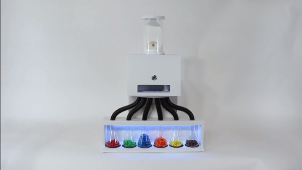
Now that the individual candies could readily be separated and fed through a machine, the rest of the project came together quickly. A color sensor was combined with servos and a stepper motor to duct M&Ms into separate flasks.

The real value of this build, however, is in the overall attention paid to the aesthetics of the final product. The device was built to be a kinetic sculpture, able to run reliably with the minimum of attention at the behest of even an untrained user. By carefully optimising the mechanisms inside and building an attractive enclosure, [Karl] has developed something we’d be proud to show off in a living room.

 

The Noisiest Seven-Segment Display Ever

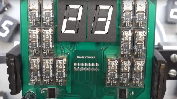
Few mechanical clocks are silent, and many find the sounds they make pleasant. But the stately ticking of an old grandfather clock or the soothing sound of a wind-up alarm clock on the nightstand are nothing compared to the clattering cacophony that awaits [ProtoG] when he finishes the clock that this electromechanical decimal to binary to hex converter and display will be part of.

Undertaken as proof of concept before committing to a full six digit clock build, we’d say [ProtoG] is hitting the mark. Yes, it’s loud, but the sound is glorious. The video below shows the display being put through its paces, and when the clock rate ramps up, the rhythmic pulsations of the relays driving the seven-segment flip displays is hypnotizing. The relays, one per segment of the Alfa Zeta flip displays, have DPDT contacts wired to flip a segment by reversing polarity. As a work in progress, [ProtoG] hasn’t shared many more details yet, but he promises to keep us up to date on the converter aspect of the circuit. Right now it just seems like a simple but noisy driver. We’ll be following this one with interest.

If you prefer your clocks quieter but still like funky displays, check out this mixed media circus-themed clock.

Continue reading “The Noisiest Seven-Segment Display Ever”

The Tiniest Working 68K System

68000 microprocessors appeared in the earliest Apple Macintoshes, the Commodore Amiga and Atari ST, and the Sega Genesis/Mega Drive among other familiar systems. If you were alive during the 16-bit era, there is a good chance that you will have owned a Motorola 68000 or one of its derivatives in a computer or game console. By the end of the 1990s it was clear that the 68K line had had its day on the desktop, but a new life for it at the consumer level was found in the PDA market. The first Motorola Dragonball was a 68000 series system-on-chip, and it was a few of these in a BGA package that [Plasmode] had in stock after ordering them in error believing them to be in a different package.

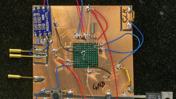
The Dragonball 68328 has an interesting bootstrap mode allowing it to run with no external ROM or RAM, and with only a serial connection to the outside world. Recognising this as having the potential for the smallest possible 68K system, he proceeded to make it happen with some impressive soldering direct to the solder balls of an upturned BGA package.

On a piece of PCB material are simply the 68328, a 32.768kHz crystal and capacitors, a MAX232 circuit for an RS232 serial connection, a reset button, and a power regulator. Using the Motorola DOS debug software which is still available for download after all these years, he was able to connect to his tiny 68K computer and run code. It’s not entirely useful, but of all the possible 68K configurations it has to be the smallest.

This isn’t the first minimal computer using only a processor chip and serial link, in the past we’ve shown you a PDP-11 in the same vein.

Amazing Mechanical Linkages And The Software To Design Them

Most of us are more bits-and-bytes than nuts-and-bolts, but we have the deepest appreciation for the combination of the two. So, apparently, does [rectorsquid]. Check out the design and flow of his rolling ball sculpture (YouTube, embedded below) to see what we mean. See how the arms hesitate just a bit as the ball is transferred? See how the upper arm gently places it on the ramp with a slight downward gesture? See how it’s done with one motor? There’s no way [rectorsquid] designed this on paper, right?

Of course he didn’t (YouTube). Instead, he wrote a simulator that lets him try out various custom linkages in real time. It’s a Windows-only application (sigh), but it’s free to use, while the video guides (more YouTube) look very comprehensive and give you a quick tour of the tool. Of special note is that [rectorsquid]’s software allows for sliding linkages, which he makes very good use of in the rolling ball sculpture shown here.

We’ve actually secretly featured [rectorsquid]’s Linkage software before, in this writeup of some amazing cosplay animatronic wings that used the program for their design. But we really don’t want you to miss out if you’re doing mechanical design and need something like this, or just want to play around.

If you’d like to study up on your nuts and bolts, check out our primer on the ubiquitous four-bar linkage, or pore through Hackaday looking for other great linkage-powered examples, like this automatic hacksaw or a pantograph PCB probe for shaky hands.

Anyone know of an open-source linkage simulator that can also output STL files for 3D printing? Or in any format that could be easily transformed into OpenSCAD? Asking for a “friend”.

Continue reading “Amazing Mechanical Linkages And The Software To Design Them”

Repairing A Sunburned Game Boy Screen

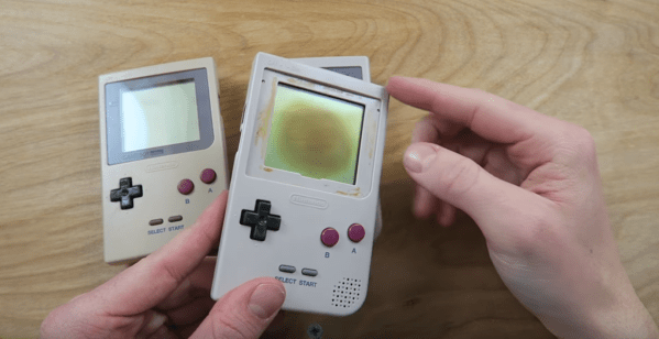
The original Game Boy is a classic. Sure, it had no backlight, but there is something special about playing on that classic green screen. Unfortunately, some of these older systems are suffering a terrible fate — screen burn. Game Boy’s played best with lots of light — especially out in the sun. But that same sun did terrible things to the screen. A black splotch in the center of the LCD is the telltale sign of a burned Game Boy. You might think that screen replacement is the only option, but [The Retro Future] shows us how to repair this issue.

A reflective LCD is a layer cake made up of polarizers, two panes of glass, and a reflector. The burns often seen on Game Boy screens usually are in the polarizer and the optically clear glue which attaches the plastic polarizer to the glass. We’re guessing these burns happen when someone leaves their Game Boy out in the sun. Between the sun rays directly striking the top polarizer and the rays bounced back from the reflector at the rear of the screen, that poor polarizer doesn’t stand a chance.

Repairing the burn is a delicate operation, as one false move could crack the thin LCD glass. The first step is to carefully peel off the burned polarizer. This leaves a mess of dried glue, which can be scraped off or dissolved with alcohol. A new linear polarizer can then be placed on the front of the screen. [The Retro Future] chose not to glue the polarizer, but we’re betting some UV cure LOCA (Liquid Optically Clear Adhesive) from a cell phone screen protector would do the trick.

If you love the look of the classic Game Boy, but want to play just about any classic game, grab a Raspberry Pi zero, and build a retro Pi Boy.

Continue reading “Repairing A Sunburned Game Boy Screen”

Cramming A Pi Zero Into A Cheap Handheld Game

At this point, we’ve seen the Raspberry Pi jammed into what amounts to every retro game system, handheld or otherwise, that was ever released. While they’re always fun builds, invariably somebody will come along who is upset that the original hardware had to be gutted to create it. It seems as if with each post, a classic gaming aficionado out there has his or her heart broken just a bit more. Will no one put an end to the senseless slaughter of Game Boys?

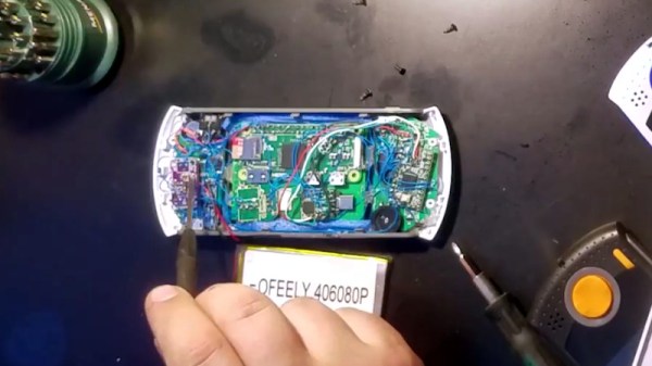
As it so happens, not all hardware modders are such unconscionable brutes. [Starfire] recently sent his latest creation into the tip line, and it’s designed specifically to address the classic gaming massacre in which Hackaday has so shamefully been a collaborator.  His build sacrifices a portable Genesis built by AtGames, and turns it into a Raspberry Pi Zero portable running RetroPie.

Opening up the back panel of his portable Pi shows an incredible amount of hardware smashed into the tiny package. Beyond the obvious Pi Zero, there’s a iUniker 2.8-inch LCD, a 2,200 mAh battery, a two-port USB hub, a Teensy microcontroller, a USB sound card, an audio amplifier, a LiPo charging module, and a boost converter. [Starfire] measured peak power consumption to be 500 mA, which should give about a 3.5 hour run time on the 2,200 mAh battery.

This is all the more impressive when you realize the original AtGames PCB is still in the system, albeit with the center cut out for the Pi’s LCD to fit in. Rather than having to figure out a new way to handle input, [Starfire] simply connected the existing inputs to the digital pins on the Teensy and used some code to convert that into USB HID for the Pi. A few case modifications were necessary, namely the removal of the battery compartment from the back panel and covering up the original SD card slot and ports; but otherwise the finished product looks completely stock.

If you don’t mind tearing into a real Game Boy to make your portable Pi, you can check out a few of the stand out examples which we’ve covered here in the past.

Continue reading “Cramming A Pi Zero Into A Cheap Handheld Game”

Three Ways To Etch Snazzy Brass Nameplates

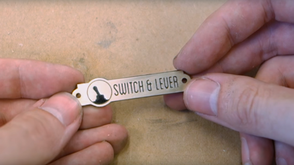
It’s the little touches that make a project, and a nice nameplate can really tie a retro build together. Such badges are easy enough to make with a CNC machine, but if you don’t have access to machine tools you can put chemistry to work for you with these acid-etched brass nameplates.

The etching method that [Switch and Lever] uses to get down to brass plaques will be intimately familiar to anyone who has etched a PCB before. Ferric chloride works as well on brass as it does on copper, and [Switch and Lever] does a good job explaining the chemistry of the etching process and offers some tips on making up etching solution from powdered ferric chloride. But the meat of the video below is the head-to-head test of three different masking methods.

The first method uses a laser printer and glossy paper ripped from a magazine to create a mask. The toner is transferred to the brass using an office laminator, and the paper removed with gentle rubbing before etching. For the other two candidates he uses a laser engraver to remove a mask of plain black spray paint in one case, or to convert special laser marking paint to a mask in the other.

We won’t spoil the surprise as to which gave the best results, but we think you’ll be pleased with how easy making classy nameplates can be. You can also use electrolytic methods for a deeper etch, but we think acid etching is a little more approachable for occasional use.

Continue reading “Three Ways To Etch Snazzy Brass Nameplates”