Non-Arduino Powered By A Piece Of Computing History

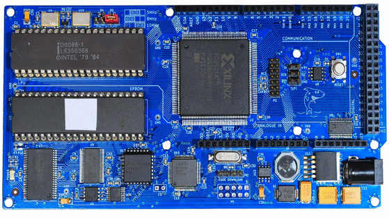
Sometimes it is a blessing to have some spare time on your hands, specially if you are a hacker with lots of ideas and skill to bring them to life. [Matt] was lucky enough to have all of that and recently completed an ambitious project 8 months in the making – a Non-Arduino powered by the giant of computing history – Intel’s 8086 processor. Luckily, [Matt] provides a link to describe what Non-Arduino actually means; it’s a board that is shield-compatible, but not Arduino IDE compatible.

He was driven by a desire to build a single board computer in the old style, specifically, one with a traditional local bus. In the early days, a System Development Kit for Intel’s emerging range of  microprocessors would have involved a fair bit of discrete hardware, and software tools which were not all too easy to use.

Back in his den, [Matt] was grappling with his own set of challenges. The 8086 is a microprocessor, not a microcontroller like the AVR, so the software side of things are quite different. He quickly found himself locking horns with complex concepts such as assembly bootstrapping routines, linker scripts, code relocation, memory maps, vectors and so on. The hardware side of things was also difficult. But his goal was learning so he did not take any short cuts along the way.

[Matt] documented his project in detail, listing out the various microprocessors that run on his 8OD board, describing the software that makes it all run, linking to the schematics and source code. There’s also an interesting section on running Soviet era (USSR) microprocessor clones on the 8OD. He is still contemplating if it is worthwhile building this board in quantities, considering it uses some not so easy to source parts. If you are interested in contributing to the project, you could get lucky. [Matt] has a few spares of the prototypes which he is willing to loan out to anyone who can can convince him that they could add some value to the project.

Continue reading “Non-Arduino Powered By A Piece Of Computing History”

Wireless Water Level Sensor From PVC Pipe

[Bob] was having trouble keeping up with his water troughs. He had to constantly check them to make sure they weren’t empty, and he always found that the water level was lower than he thought. He decided it was time to build his own solution to this problem. What he ended up with was a water level sensor made from PVC pipe and a few other components.

The physical assembly is pretty simple. The whole structure is made from 1/2″ PVC pipe and fittings and is broken into four nearly identical sensor modules. The sensors have an electrode on either side. The electrodes are made from PVC end caps, sanded down flat at the tip. A hole is then drilled through the cap to accommodate a small machine screw. The screw threads are coated in joint compound before the screw is driven into the hole, creating its own threads. These caps are placed onto small sections of PVC pipe, which in turn connect to a four-way PVC cross connector. 

On the inside of the electrode cap, two washers are placed onto the screw. A stranded wire is placed between the washers and then clamped in place with a nut. All of the modules are connected together with a few inches of pipe. [Bob] measured this out so it would fit appropriately into his trough, but the measurements can easily be altered to fit just about any size container. The wires all route up through the pipe. The PVC pipe is cemented together to keep the water out. The joint compound prevents any leaks at the electrodes.

A piece of CAT 5 cable connects the electrodes to the electronics inside of the waterproof controller box. The electronics are simple. It’s just a simple piece of perfboard with an XBee and a few transistors. The XBee can detect the water level by testing for a closed circuit between the two electrodes of any sensor module. The water acts as a sort of switch that closes the circuit. When the water gets too low, the circuit opens and [Bob] knows that the water level has lowered. The XBee is connected to a directional 2.4GHz antenna to ensure the signal reaches the laptop several acres away. Continue reading “Wireless Water Level Sensor From PVC Pipe”

Watt Meter Build Walks You Through Power Measurement Basics

You almost never hear of a DC Watt Meter – one just does some mental math with Volts and Amps at the back of one’s head. An AC Watt Meter, on the other hand, can by pretty useful on any workbench. This handy DIY Digital AC Watt Meter not only has an impressive 30A current range, but is designed in a hand-held form factor, making it easy to carry around.

The design from Electro-Labs provides build instructions for the hardware, as well as the software for the PIC micro-controller at its heart. A detailed description walks you through the schematic’s various blocks, and there’s also some basics of AC power measurement thrown in for good measure. The schematic and board layout are done using SolaPCB – a Windows only free EDA tool which we haven’t heard about until now. A full BoM and the PIC code round off the build. On the hardware side, the unit uses MCP3202 12 bit ADC converters with SPI interface, making it easy to hook them up to the micro-controller. A simple resistive divider for voltage and an ACS-712  Hall Effect-Based Linear Current Sensor IC are the main sense elements. Phase calculations are done by the micro-controller. The importance of isolation is not overlooked, using opto-isolators to keep the digital section away from the analog. The board outline looks like it has been designed to fit some off-the-shelf hand-held plastic enclosure (if you can’t find one, whip one up from a 3D printer).

Although the design is for 230V~250V range, it can easily be modified for 110V use by changing a few parts. Swap the transformer, change the Resistive voltage divider values, maybe some DC level shifting, and you’re good to go. The one feature that would be a nice upgrade to this meter would be Energy measurements, besides just Power. For an inside look at how traditional energy meters work, head over to this video where [Ben Krasnow] explains KiloWatt Hour Meters


Video Voice Visualization

For their ECE 4760 final project at Cornell, [Varun, Hyun, and Madhuri] created a real-time sound spectrogram that visually outputs audio frequencies such as voice patterns and bird songs in gray-scale video to any NTSC television with no noticeable delay.

The system can take input from either the on-board microphone element or the 3.5mm audio jack. One ATMega1284 microcontroller is used for the audio processing and FFT stage, while a second ‘1284 converts the signal to video for NTSC output. The mic and line audio inputs are amplified individually with LM358 op-amps. Since the audio is sampled at 8KHz, a low-pass filter gets rid of frequencies above 4KHz.

After the break, you can see the team demonstrate their project by speaking and whistling bird calls into the microphone as well as feeding recorded bird calls through the line input. They built three controls into the project to freeze the video, slow it down by a factor of two, and convert between linear and logarithmic scales. There are also short clips of the recorded bird call visualization and an old-timey dial-up modem.

Continue reading “Video Voice Visualization”

CAMdrive

CAMdrive Is An Open Source Time-lapse Photography Controller

[Nightflyer] has been working on an open source project he calls CAMdrive. CAMdrive is designed to be a multi-axis controller for time-lapse photography. It currently only supports a single axis, but he’s looking for help in order to expand the functionality.

You may already be familiar with the idea of time-lapse photography. The principal is that your camera takes a photo automatically at a set interval. An example may be once per minute. This can be a good way to get see gradual changes over a long period of time. While this is interesting in itself, time-lapse videos can often be made more interesting by having the camera move slightly each time a photo is taken. CAMdrive aims to aid in this process by providing a framework for building systems that can pan, tilt, and slide all automatically.

The system is broken out into separate nodes. All nodes can communicate with each other via a communication bus. Power is also distributed to each node along the bus, making wiring easier. The entire network can be controlled via Bluetooth as long as any one of the nodes on the bus include a Bluetooth module. Each node also includes a motor controller and corresponding motor. This can either be a stepper motor or DC motor.

The system can be controlled using an Android app. [Nightflyer’s] main limitation at the moment is with the app. He doesn’t have much experience programming apps for Android and he’s looking for help to push the project forward. It seems like a promising project for those photography geeks out there. Continue reading “CAMdrive Is An Open Source Time-lapse Photography Controller”

A Camera With Computer Vision

Computer vision is a tricky thing to stuff into a small package, but last year’s Hackaday Prize had an especially interesting project make it into the 50 top finalists. The OpenMV is a tiny camera module with a powerful microcontroller that will detect faces, take a time-lapse, record movies, and detect specific markers or colors. Like a lot of the great projects featured in last year’s Hackaday Prize, this one made it to Kickstarter and is, by far, the least expensive computer vision module available today.

[Ibrahim] began this project more than a year ago when he realized simple serial JPEG cameras were ludicrously expensive, and adding even simple machine vision tasks made the price climb even higher. Camera modules that go in low-end cell phones don’t cost that much, and high-power ARM microcontrollers are pretty cheap as well. The OpenMV project started, and now [Ibrahim] has a small board with a camera that runs Python and can be a master or slave to Arduinos or any other microcontroller board.

The design of the OpenMV is extraordinarily clever, able to serve as a simple camera module for a microcontroller project, or something that can do image processing and toggle a few pins according to logic at the same time. If you’ve ever wanted a camera that can track an object and control a pan/tilt servo setup by itself, here you go. It’s a very interesting accessory for robotics platforms, and surely something that could be used in a wide variety of projects.

baby holding IC chip

Ask Hackaday: Your Very First Microcontroller

Necessity is the mother of invention. It is also true that invention necessitates learning new things. And such was the case on the stormy Tuesday morning our story begins.  Distant echos of thunder reverberated in the small 8 x 16 workshop, drawing my attention to the surge suppressor powering my bench.  With only a few vacation days left, my goal of finishing the hacked dancing Santa Claus toy was far from complete. It was for a Secret Santa gift, and I wanted to impress. The Santa moved from side to side as it sang a song. I wanted to replace the song with a custom MP3 track. In 2008, MP3 players were cheap and ripe for hacking. They could readily be picked up at local thrift shops, and I had picked up a few. It soon became clear, however, that I would need a microcontroller to make it do what I wanted it to do.

Continue reading “Ask Hackaday: Your Very First Microcontroller”