The earliest piston engines typically had only one cylinder, and at best, produced horsepower measured in single digits. But once you have a working engine, it’s a relatively short step to adding cylinders and increasing the power output. [Emiel] made a similar upgrade to one of his engines recently, upgrading it from one cylinder to four. But this isn’t an internal combustion engine, it gets its power from electric solenoids.
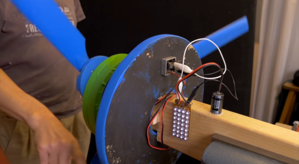
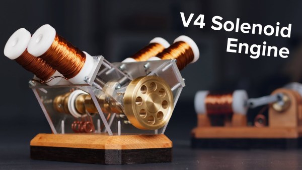
We featured his single-cylinder build about a month ago, and since then he’s been busy with this impressive upgrade. The new engine features four cylinders arranged in a V4 pattern. Of course, this greatly increases the mechanical complexity. To start, he had to machine a crankshaft to connect all four “pistons” to a shared output shaft. He also had to build a set of cams in order to time the firing of the cylinders properly, so they don’t work against one another.
The build is just as polished and impressive as the last, which is saying a lot. [Emiel] has a quality machine shop and built the entire motor from scratch, including winding the solenoids, machining the connecting rods and shafts, and building a very picturesque wooden base for the entire contraption to sit on. It’s definitely worth checking out.