Recreating The Analog Beauty Of A Vintage Tektronix Oscillator

Tektronix must have been quite a place to work back in the 1980s. The company offered a bewildering selection of test equipment, and while the digital age was creeping in, much of their gear was still firmly rooted in the analog world. And some of the engineering tricks the Tek wizards pulled off are still the stuff of legend.

One such gem of analog design was the SG505, an ultra-low-distortion oscillator module that [Paul] is trying to replicate with modern parts. That’s a tall order since not only did the original specs on this oscillator call for less than 0.0008% total harmonic distortion over a frequency range of 20 Hz to 20 kHz, but a lot of the components it used are no longer manufactured. Tek also tended to use a lot of custom parts, especially mechanical ones like the barrel switch used to select attenuation levels in the SG505, leaving [Paul] no choice but to engineer his way around them.

So far, [Paul] has managed to track down most of the critical components or source suitable substitutes. One major win was locating the original J-FET Tek used in the oscillator’s AGC circuit. One part that’s proven more elusive is the potentiometer that Tek used to adjust the frequency; who knew that finding a dual-gang precision wirewound 10k single-turn pot with no physical stop would be such a chore?

[Paul] still seems to be very much in the planning stages of this project yet, and that’s probably for the best since projects such as these live and die on proper planning. We’re keen to see how this develops, and we’re very much looking forward to seeing the FFT results. We also imagine he’ll be busting out his custom curve tracer at some point in the build, too.

Fundamentals Of FMCW Radar Help You Understand Your Car’s Point Of View

Pretty much every modern car has some driver assistance feature, such as lane departure and blind-spot warnings, or adaptive cruise control. They’re all pretty cool, and they all depend on the car knowing where it is in space relative to other vehicles, obstacles, and even pedestrians. And they all have another thing in common: tiny radar sensors sprinkled around the car. But how in the world do they work?

If you’ve pondered that question, perhaps after nearly avoiding rear-ending another car, you’ll want to check out [Marshall Bruner]’s excellent series on the fundamentals of FMCW radar. The linked videos below are the first two installments. The first covers the basic concepts of frequency-modulated continuous wave systems, including the advantages they offer over pulsed radar systems. These advantages make them a great choice for compact sensors for the often chaotic automotive environment, as well as tasks like presence sensing and factory automation. The take-home for us was the steep penalty in terms of average output power on traditional pulsed radar systems thanks to the brief time the radar is transmitting. FMCW radars, which transmit and receive simultaneously, don’t suffer from this problem and can therefore be much more compact.

Continue reading “Fundamentals Of FMCW Radar Help You Understand Your Car’s Point Of View”

Hackaday Links Column Banner

Hackaday Links: August 18, 2024

They’re back! The San Francisco autonomous vehicle hijinks, that is, as Waymo’s fleet of driverless cars recently took up the fun new hobby of honking their horns in the wee hours of the morning. Meat-based neighbors of a Waymo parking lot in the South Market neighborhood took offense at the fleet of autonomous vehicles sounding off at 4:00 AM as they shuffled themselves around in the parking lot in a slow-motion ballet of undetermined purpose. The horn-honking is apparently by design, as the cars are programmed to tootle their horn trumpets melodiously if they detect another vehicle backing up into them. That’s understandable; we’ve tootled ourselves under these conditions, with vigor, even. But when the parking lot is full of cars that (presumably) can’t hear the honking and (also presumably) know where the other driverless vehicles are as well as their intent, what’s the point? Luckily, Waymo is on the case, as they issued a fix to keep the peace. Unfortunately, it sounds like the fix is just to geofence the lot and inhibit honking there, which seems like just a band-aid to us.

Continue reading “Hackaday Links: August 18, 2024”

Your Text Needs More JPEG

We’ve all been victims of bad memes on the Internet, but they’re not all just bad jokes gone wrong. Some are simply bad as a result of being copies-of-copies, as each reposter adds another layer of compression to an already lossy image format like JPEG. Compression can certainly be a benefit in areas like images and videos, but [Michal] had a bit of a fever dream imagining this process applied to text. Rather than let the idea escape, he built the Lossifizer to add JPEG-like compression to text.

JPEG compression uses a system similar to the fast Fourier transform (FFT) called the discrete cosine transform (DCT) to reduce the amount of data in an image by essentially removing some frequency information. The data lost is often not noticeable to the human eye, at least until it gets out of hand. [Michal]’s system performs the same transform on text instead, with a slider to control the “amount of JPEG” in the output text. The code for this script uses a “perceptual” character map, clustering similarly-looking and similarly-sounding characters next to each other, resembling “leet speak” from days of yore, although at high enough compression this quickly gets out of hand.

One of the quirks that [Michal] discovered is that certain AI chat bots have a much less difficult time interpreting this JPEG-ified text than a human probably would have, which provides a bit of insight into how some of these algorithms might be functioning under the hood. For some more insight into how JPEG actually works on images, we posted about a deep dive into the image format a while back.

Doppler Speed Sensor Puts FFT And AGC To Work

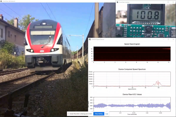
Some people hate to revisit projects that are done and dusted. We get that; it’s a little like reading a book you’ve already read when there are so many others to choose from. But rereading a book sometimes reveals subtle nuances you missed the first time around, and revisiting projects can be much the same, as with this new and improved Doppler radar speed sensor.

We seem to have been remiss in writing up [Limpkin]’s last go-around with the CDM324 microwave module, a 24-GHz transceiver that you can pick up on the cheap from the usual sources, but we’ve featured this handy little module in plenty of other projects. [Limpkin]’s current project uses the same module to create a Doppler speed sensor, but with a little more sophistication all around. Whereas the original used a simple comparator to output a square wave that’s proportional to the Doppler shift and displayed the speed on a simple terminal session, version two takes a different tack.

First, [Limpkin] opted to implement the whole sensor in hardware. The front end is quite different — an op-amp with 84 dB of gain followed by an automatic gain control (AGC) stage built from a MAX9814 microphone preamp. Extraction of the speed from the module output is left to an STM32F301 running an FFT algorithm on the signal coming out of the analog circuit, which essentially picks out the biggest peak in the spectrum and calculates the Doppler shift from that, displaying the results on an LCD display.

Of course, as a [Limpkin] project, there’s a lot more to it than just that. The write-up is very detailed, going down a few enjoyable rabbit holes like characterizing the amplification chain and diving into the details of Johnson-Nyquist noise to chase down stray oscillations. There’s some great stuff here, and it’s well worth a deep read; there’s also the video below that lets you see (and hear) what’s going on.

Continue reading “Doppler Speed Sensor Puts FFT And AGC To Work”

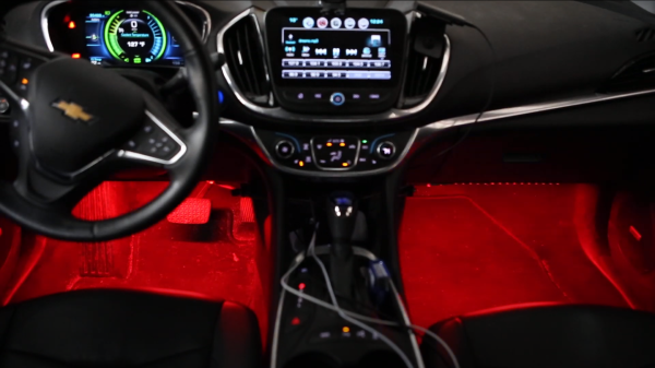
A view of the inside of a car, with drivers wheel on the left and control panel in the middle, with red LED light displayed in the floor area under the drivers wheel and passenger side.

Bass Reactive LEDs For Your Car

[Stephen Carey] wanted to spruce up his car with sound reactive LEDs but couldn’t quite find the right project online. Instead, he wound up assembling a custom bass reactive LED display using an ESP32.

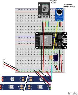
A schematic of the Bass LED reactive circuit, with an ESP32 on a breadboard connected to a KY-040 encoder module, a GY-MAX4466 microphone module and LED strips below.

The entirety of the build is minimal, consisting of a GY-MAX4466 electret microphone module, a KY-040 encoder for some user control and an ESP32 attached to a Neopixel strip. The only additional electronic parts are some passive resistors to limit current on the data lines and a capacitor for power line noise suppression. [Stephen] uses various enclosures from Thingiverse for the microphone, rotary encoder and ESP32 box to make sure all the modules are protected and accessible.

The magic, of course, is in the software, with the CircuitPythyon ulab library used to do the heavy lifting of creating the spectrogram and frequency filtering. [Stephen] has made the code is available on GitHub for those wanting to take a closer look.

It wasn’t very long ago that sound reactive LEDs used to be a heavy lift, requiring optimized FFT libraries or specialized components to do the spectrogram. With faster and cheaper microcontroller boards, we’re seeing many great projects, like the sensory bridge or Raspberry Pi driven LED spectrogram, that can now take spectrograms and Fourier transform calculations as basic infrastructure to build on top of them. We’re happy to see [Stephen] leverage the ESP32’s speed and various circuit Python libraries to create a very cool LED car hack.

Video after the break!

Continue reading “Bass Reactive LEDs For Your Car”

The Fastest Fourier Transform In The West

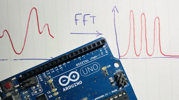
An interesting aspect of time-varying waveforms is that by using a trick called a Fourier Transform (FT), they can be represented as the sum of their underlying frequencies. This mathematical insight is extremely helpful when processing signals digitally, and allows a simpler way to implement frequency-dependent filtration in a digital system. [klafyvel] needed this capability for a project, so started researching the best method that would fit into an Arduino Uno. In an effort to understand exactly what was going on they have significantly improved on the code size, execution time and accuracy of the previous crown-wearer.

A complete real-time Fourier Transform is a resource-heavy operation that needs more than an Arduino Uno can offer, so faster approximations have been developed over the years that exchange absolute precision for speed and size. These are known as Fast Fourier Transforms (FFTs). [klafyvel] set upon diving deep into the mathematics involved, as well as some low-level programming techniques to figure out if the trade-offs offered in the existing solutions had been optimized. The results are impressive.

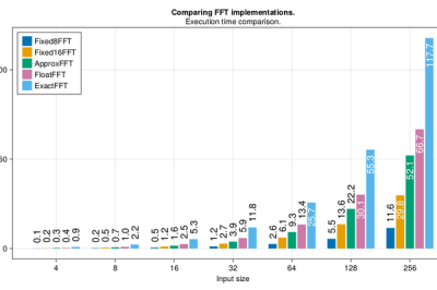
Fastest FFT code benchmarking results in ms
Benchmarking results showing speed of implementation versus the competition (ApproxFFT)

Not content with producing one new award-winning algorithm, what is documented on the blog is a masterclass in really understanding a problem and there are no less than four algorithms to choose from depending on how you rank the importance of execution speed, accuracy, code size or array size.

Along the way, we are treated to some great diversions into how to approximate floats by their exponents (French text), how to control, program and gather data from an Arduino using Julia, how to massively improve the speed of the code by using trigonometric identities and how to deal with overflows when the variables get too large. There is a lot to digest in here, but the explanations are very clear and peppered with code snippets to make it easier and if you have the time to read through, you’re sure to learn a lot!  The code is on GitHub here.

If you’re interested in FFTs, we’ve seen them before around these parts. Fill your boots with this link of tagged projects.