We are all used to the op-amp, as a little black box from which we can derive an astonishingly useful range of circuit functions. But of course within it lurks a transistor circuit on a chip, and understanding the operation of that circuit can give us insights into the op-amp itself. It’s a subject [IMSAI Guy] has tackled during the lockdown, recording a set of videos explaining a simple discrete-component op-amp.
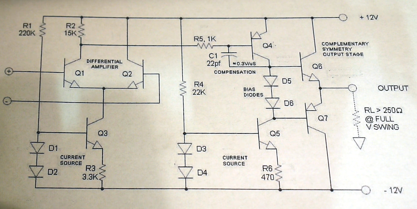
He starts with the current source, a simple circuit of two diodes, a resistor, and a transistor that sets the bias for the two-transistor differential amplifier. This is followed by a look at the output driver, and we would expect that shortly to come will be a video on the output itself. Start the series with the first episode, which we’ve placed below the break.
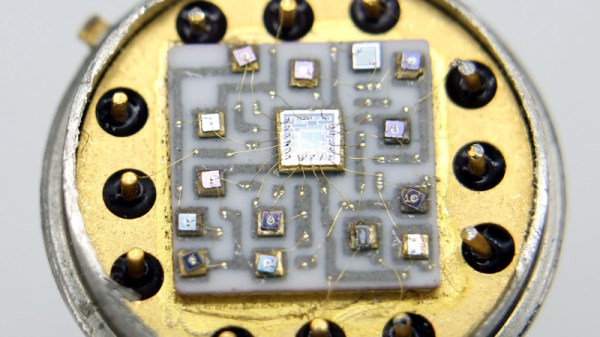
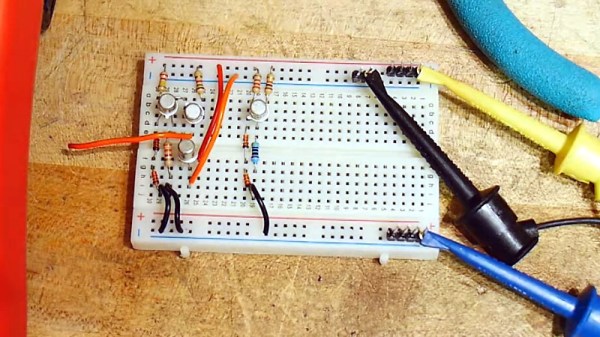
His style is laid-back, making it a restful watch as he builds each circuit on a breadboard and explains its operation with the aid of a multimeter. If this whets your appetite for more on simple op-amps, we looked at the first integrated circuit op-amp back in 2018.