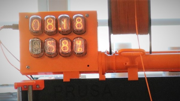
CPU Made From 74HC Chips Is A Glorious Mess

Did you ever start a project that you felt gained a life of its own? This project by [Paulo Constantino] is an entire CPU named dreamcatcher on breadboards, and is a beautiful jungle of digital. On top of that, it works to connect to an analog VGA display. How cool is that!

Designing an ALU and then a CPU is a typical exercise for students of digital design and is done using VerilogHDL or VHDL. It involves creating an ALU that can add, subtract etc while a control unit manages data moves and the like. There is also a memory fetch and instruction decode made up of de-mulitiplexers and a bunch of flip-flops that make up registers and flags. They are as complex as they sound if not more.

[Paulo Constantino] went ahead and designed the whole thing in Eagle as a schematic using 74HC logic chips. To build it though instead of a PCB he used breadboards. Everything from bus decoders to controlling an external VGA display is done using jumper wires. We did cover a video on the project a while back, but this update adds a video card interface to the build.

The CPU updates the display buffer on the VGA card, and in the video below shows the slow and steady update. The fact that the jungle of wires can drive a display is awesome. He has since started working on a 16-bit version of the processor and we’d love to see someone take it up a notch.

For those more accustomed to the PCB, the Z80 membership card project is a great build for 8-bit computer fans.

Thanks to [analog engineer] for the tip.

Continue reading “CPU Made From 74HC Chips Is A Glorious Mess”

LED Matrix And A Phototransistor Make A Reverse Camera

A digital camera has an array of sensors that captures light reflected or transmitted onto it. This build is something closer to a reverse camera – a single sensor that makes images on a matrix of LEDs. And we think it’s pretty neat.

We have to admit to being a little confused by [marciot]’s LED matrix scanner when we first stumbled upon it. From the video below we thought that the LEDs in the matrix were being used both to detect incident light and as a display. We’ve seen LEDs used as photodiodes before, so such a contraption could work, but that’s not what’s going on here. A phototransistor is wired to an Arduino Uno and positioned above a 32×32 RGB LED matrix. A scanning routine rasters over the LEDs in the matrix while the sensor watches, and then the program turns on the LEDs that the sensor saw during the scan. Positioned far above the matrix, a large disc of light results, making it look like the phototransistor is beaming light down onto the matrix. The effect is reinforced by placing something between the sensor and the matrix, which casts a virtual shadow. Used close to the LEDs the sensor acts more like a light pen.

It’s a cool effect and it looks like a fun project to throw together. Refresh time could perhaps be a bit snappier, though; maybe an ESP32 could help with that.

Continue reading “LED Matrix And A Phototransistor Make A Reverse Camera”

Flex PCBs Make Force-Mapping Pressure Sensor For Amputee

What prosthetic limbs can do these days is nothing short of miraculous, and can change the life of an amputee in so many ways. But no matter what advanced sensors and actuators are added to the prosthetic, it has to interface with the wearer’s body, and that can lead to problems.

Measuring and mapping the pressure on the residual limb is the business of this flexible force-sensing matrix. The idea for a two-dimensional force map came from one of [chris.coulson]’s classmates, an amputee who developed a single-channel pressure sensor to help him solve a painful fitting problem. [chris.coulson] was reminded of a piezoresistive yoga mat build from [Marco Reps], which we featured a while back, and figured a scaled-down version might be just the thing to map pressure points across the prosthetic interface. Rather than the expensive and tediously-applied web of copper tape [Marco] used, [chris] chose flexible PCBs to sandwich the Velostat piezoresistive material. An interface board multiplexes the 16 elements of the sensor array to a PIC which gathers and records testing data. [chris] even built a test stand with a solenoid to apply pressure to the sensor and test its frequency response to determine what sorts of measurements are possible.

We think the project is a great application for flex PCBs, and a perfect entry into our Flexible PCB Contest. You should enter too. Even though [chris] has a prototype, you don’t need one to enter: just an idea would do. Do something up on Fritzing, make a full EAGLE schematic, or just jot a block diagram down on a napkin. We want to see your ideas, and if it’s good enough you can win a flex PCB to get you started. What are you waiting for?

Vintage Programmer Gets Modern Chip Adapter

While trying to revive a Donkey Kong Jr arcade board, [Jelmer Bruijn] found himself in the market for an EPROM programmer and became the proud owner of a 1990’s era Dataman S4. Despite its age, it’s a fairly nice tool which allows you to read and write a laundry list of different EPROM types, all without being tied to a computer. The only catch is that a few types of chips need an adapter to work in the Dataman S4, some of which are unsurprisingly no longer available.

After some above and beyond support from the current crew at Dataman set him on the right track, [Jelmer] decided to try his hand at reverse engineering how the old adapters worked so he could build his own. His ultimate goal was to read 40 pin EPROMs on the 32 pin Dataman S4, but in the end he says the information he gathered should be applicable for building other adapters if you ever find yourself in need of such things.

As you might expect, there’s a bit more to the project than a simple pin adapter. [Jelmer] assumed some kind of shift register or latching arrangement would be required to make up for the shortage of pins on the Dataman S4’s ZIF socket. It was just a matter of figuring out how it all went together.

Luckily, [Jelmer] found that the programmer would happily attempt to perform operations on a 16 bit EPROM even though no adapter was physically present. This gave him a chance to probe around with a logic analyzer to figure out what it was trying to accomplish. The trick turned out to be splitting the 16 bit bus into two 8 bit buses which are requested sequentially.

With careful observation, close studying of 16 bit chip datasheets, and much brow furrowing, he was eventually able to come up a design that used five 74xx573 latches and put a schematic together in Eagle. There were a few kinks to iron out when the boards finally arrived, but ultimately the design worked on the first try. [Jelmer] says the same technique should work for 42 pin EPROMs, but as Dataman still actually sell adapters for those he decided not to supply schematics for it.

[Jelmer] tells us that he was inspired to send this success story our way after reading how our very own [Elliot Williams] took the long away around to erase a couple UV EPROMs recently While this isn’t the first time we’ve seen somebody have to hack support for 16 bit EPROMs into their programmer, it’s good to see that the manufacturer at least had the customer’s back in this case.

Bixel, An Open Source 16×16 Interactive LED Array

The phrase “Go big or go home” is clearly not lost on [Adam Haile] and [Dan Ternes] of Maniacal Labs. For years they’ve been thinking of creating a giant LED matrix where each “pixel” doubled as a physical push button. Now that they’ve built up experience working on other LED projects, they finally decided it was time to take the plunge and create their masterpiece: the Bixel.

Creating the Bixel (a portmanteau of button, and pixel) was no small feat. The epic build is documented in an exceptionally detailed write-up on the team’s site, in addition to the time-lapse video included after the break. [Adam] tells us the Bixel took around 100 hours of assembly, and we don’t doubt it. This is truly one of those labors of love which is unlikely to be duplicated, though all of the source files for both the hardware and software are available if you’re feeling brave enough.

The write-up contains a lot of fascinating detail about the design and construction of the Bixel, but perhaps the least surprising of all of them is that the final product ended up being very different from what they originally envisioned. The plan was to simply use lighted arcade buttons in a 16×16 grid, as they were purpose-built for exactly what the guys had in mind. But when they priced them out, the best they could do was $2 a pop. That’s $500 for just the buttons alone, before they even got into the enclosure or electronics. Like any good hackers, [Adam] and [Dan] decided to ditch the ready-made solution and come up with something of their own.

In the end, they cut the individual LEDs out of RGB strips, and soldered them down to their custom designed 500mmx500mm PCB. To the sides of each section of strip are two tactile switches, and above is a “sandwich” made of laser cut acrylic. The sheet closest to the LEDs has a 25mm hole, the top sheet has a 20mm hole, and between them is a circle of acrylic that acts as the “button”. Once it’s all screwed together, the button can’t fall out of the front or move from side to side, but it can be pushed down to contact the tactile switches.

To wire it all up they took a cue from the DIY keyboard scene and used a Teensy, some 595 shift registers, and 256 1N4148 diodes. A Raspberry Pi running their Python framework does the heavy computational lifting, leaving the Teensy to just handle talking to the hardware. Overall it’s a fantastic design to emulate if you’re looking to create large arrays of buttons on the cheap; such as whenever you get around to building that starship simulator.

Continue reading “Bixel, An Open Source 16×16 Interactive LED Array”

Massive Shift Register Switches Lights

Sometimes you have to switch a light. Maybe it’s an LED but sometimes it’s mains-powered. That’s not too hard, a transistor and a relay should do it. If you have to switch more lights, that’s not too bad either, as long as your microcontroller has enough free GPIOs. But, if you need to switch a large number of lights, like 256 of them, for example, you’re going to need something else.

[Jan]’s project didn’t switch quite that many lights, but 157 of them is still enough of a chore to need a creative solution so he decided to use a 256-bit shift register to do the legwork. The whole thing is powered by a NodeMCU ESP8266 and was professionally built on DIN rails in a metal enclosure.

The build is interesting, both from a technical point of view and from an artistic one. It looks like it uses more than a mile of wiring, too. The source code is also available on the project page if you happen to have a need for switching a huge number of lightbulbs. Incandescent blulbs aren’t only good for art installations and lamps, though, they can also be used in interesting oscillator circuits too.

Home Made 8-Bit CPU Is A Wiry Blinky Build

It might look like a random pile of wires to some, but it is far from random: [Paulo Constantino] built this 8-bit CPU himself from scratch. He built his remarkable creation using wires and 74HC shift register chips, plus a selection of LEDs to show the various registers.

Running at a maximum of 5MHz, it has an 8-bit data and address bus, although the latter can be expanded to 16 bits. It’s not mining Bitcoin (yet), but it can do things like play the Mario theme. His latest addition is the addition of the ability to write data out to flash memory, and he is looking to add a keyboard to make programming easier.

At the moment, he has to program the CPU by setting DIP jumpers. It’s an impressive, if somewhat frightening build that [Paulo] says took him a couple of days to design and a week or so to build. We’ve seen a few breadboard CPU builds, (some of which were tidier) and builds with similar shift register chips, but this one scores big in the blinky light and mad genius stakes.

Thanks to [AnalogMind] for the tip!

Continue reading “Home Made 8-Bit CPU Is A Wiry Blinky Build”