Test PCBs On A Bed Of Nails

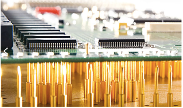
While it might be tempting to start soldering a circuit together once the design looks good on paper, experience tells us that it’s still good to test it out on a breadboard first to make sure everything works properly. That might be where the process ends for one-off projects, but for large production runs you’re going to need to test all the PCBs after they’re built, too. While you would use a breadboard for prototyping, the platform you’re going to need for quality control is called a “bed of nails“.

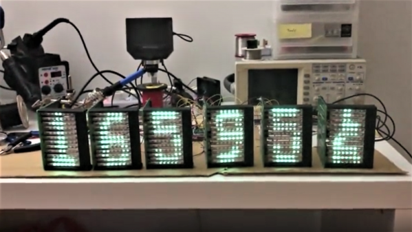
This project comes to us by way of [Thom] who has been doing a large production run of circuits meant to drive nixie tubes. After the each board is completed, they are laid on top of a number of pins arranged to mate to various points on the PCB. Without needing to use alligator clamps or anything else labor-intensive to test, this simple jig with all the test points built-in means that each board can be laid on the bed and tested to ensure it works properly. The test bed looks like a bed of nails as well, hence the name.

There are other ways of testing PCBs after production, too, but if your board doesn’t involve any type of processing they might be hard to implement. Nixie tubes are mostly in the “analog” realm so this test setup works well for [Thom]’s needs.

The Complete Beginner’s Guide To Building A CNC Machine

Despite appearances, [This Old Tony]’s latest series has little to do with CNC-ifying an Etch A Sketch. Although he certainly achieves that, more or less, automating the classic toy is just the hook for a thorough lesson in CNC machine building starting with the basics.

Fair warning: we said basics, and we mean it. [Old Tony]’s intended audience is those who haven’t made the leap into a CNC build yet and need the big picture. Part one concentrates on the hardware involved – the steppers, drivers, and controller. He starts with one of those all-in-one eBay packages, although he did upgrade the motion controller to a Mach4 compatible board; still, the lessons should apply to most hardware.

By the end of part one, the Etch A Sketch is connected to two of the steppers and everything is wired up and ready to go for part two, the first part of which is all about inputs and outputs. Again, this is basic stuff, like how relays work and why you might need to use them. But that’s the kind of stuff that can baffle beginners and turn them off to the hobby, so kudos to [Old Tony] for the overview. The bulk of the second part is about configuring Mach4 Hobby, with a ton of detail and some great tips and tricks for getting a machine ready to break some end mills.

For someone looking to get into a CNC build, [Old Tony]’s hard-won CNC experience really fills in the gaps left by other tutorials. And it looks like a third part, dealing with making all this into something more than an automated Etch A Sketch, is in the works. We’re looking forward to that.

Continue reading “The Complete Beginner’s Guide To Building A CNC Machine”

A Guide For Driving LED Matrices

Building an LED matrix is a fun project, but it can be a bit of a pain. Usually it starts with hand-soldering individual LEDs and resistors together, then hooking them up to rows and columns so they can be driven by a microcontroller of some sort. That’s a lot of tedious work, but you can order an LED matrix pre-built to save some time and headache. You’ll still need a driver though, and while building one yourself can be rewarding there are many pitfalls and trade-offs to consider when undertaking that project as well. Or, you can consider one of a number of drivers that [deshipu] has outlined in detail.

The hangups surrounding the driver board generally revolve around the issue of getting constant brightness from LEDs regardless of how many in the row or column are illuminated at one time. Since they are typically driven one row or column at a time, the more that are on the lower the brightness each LED will have. Driver boards take different approaches to solving this problem, which usually involve a combination of high-speed scanning of the matrix or using a constant-current source in order to eliminate the need for resistors. [deshipu] outlines four popular chips that achieve these purposes, and he highlights their pros and cons to help anyone looking to build something like this.

Most of these boards will get you to an 8×8 LED matrix with no problem, with a few going a few pixels higher in either direction. That might be enough for most of our needs, but for something larger you’ll need other solutions like the one found in this 64×32 LED matrix clock. There are also even more complicated drivers if you go into extra dimensions.

Photo credit: Komatta [Public domain], from Wikimedia Commons

Make The Surface Dial Do More Things, Such As MIDI

The Surface Dial is a $100+ rotary control. You can turn it, and it’ll make some basic stuff happen on your Microsoft Surface. It’s silver and sleek and elegant but fundamentally, it just works via emulated keyboard shortcuts. This doesn’t really do much for translating analog rotational motion into digital feedback in a nice way, so [SaveTheHuman5] created Elephant to fix this issue.

As standard, there are two ways to work with the Surface Dial as an end-user. The easiest way is to use existing utilities to map dial actions to shortcut keys. However, for interfacing with knobs and sliders in user interfaces, this is clunky. Instead, [SaveTheHuman5] drilled down and created their own utility using the Surface Dial API provided by Microsoft. This allows raw data to be captured from the dial and processed into whatever interactions your heart desires – as long as you’ve got the coding muscles to do it!

The Elephant software allows the knob to be used in two distinct modes – mouse capture, and MIDI. Mouse capture allows one to use a regular mouse to select UI objects, such as knobs in a music application, and then turn the Surface Dial to adjust the control. Anyone that’s struggled with tiny emulated rotary controls on a VST synth before would instantly know the value of this. In MIDI mode, however, the knob simply presents itself as a MIDI device outputting commands directly which would be more useful in performance environments in particular.

Overall, it’s a tidy hack of an otherwise quite limited piece of hardware – the only thing we’d like to see is more detail on how it was done. If you’ve got a good idea on how this could work, throw it down in the comments. And, if your thirst for rotary controls is still not satiated, check out this media controller. Video after the break.

Continue reading “Make The Surface Dial Do More Things, Such As MIDI”

Custom LCD Module Is Unexpectedly Cheap And Easy

Looking to take your project to the next level in terms of functionality and appearance? A custom LCD display might be the thing that gets you there, at least compared to the dot-matrix or seven-segment displays that anyone and their uncle can buy from the usual sources for pennies. But how does one create such a thing, and what are the costs involved? As is so often the case these days, it’s simpler and cheaper than you think, and [Dave Jones] has a great primer on designing and specifying custom LCDs.

The video below is part of an ongoing series; a previous video covered the design process, turning the design into a spec, and choosing a manufacturer; another discussed the manufacturer’s design document approval and developing a test plan for the module. This one shows the testing plan in action on the insanely cheap modules – [Dave] was able to have a small run of five modules made up for only $138, which included $33 shipping. The display is for a custom power supply and has over 200 segments, including four numeric sections, a clock display, a bar graph, and custom icons for volts, amps, millijoules, and watt-hours. It’s a big piece of glass and the quality is remarkable for the price. It’s not perfect – [Dave] noted a group of segments on the same common lines that were a bit dimmer than the rest, but was able to work around it by tweaking the supply voltage a bit.

We’re amazed at how low the barrier to entry into custom electronics has become, and even if you don’t need a custom LCD, at these prices it’s tempting to order one just because you can. Of course, you can also build your own LCD display completely from scratch too.

Continue reading “Custom LCD Module Is Unexpectedly Cheap And Easy”

Dual Brushed Motor Controller Doesn’t Care How It Receives Commands

The simple DC brushed motor is at the heart of many a robotics project. For making little toy bots that zip around the house, you can’t beat the price and simplicity of a pair of brushed motors. They’re also easy to control; you could roll your own H-bridge out of discrete transistors, or pick up one of the commonly used ICs like the L298N or L9110S.

But what if you want an all-in-one solution? Something that will deliver enough current for most applications, drive dual motors, and deal with a wide range of input voltages. Most importantly, something that will talk to any kind of input source.  For his Hackaday prize entry, [Praveen Kumar] is creating a dual brushed motor controller which can handle a multitude of input types. Whether you’re using an IR remote, a Pi communicating over I2C, an analog output or Bluetooth receiver, this driver can handle them all and will automatically select the correct input source.

The board has an ATmega328p brain, so Arduino compatibility is there for easy reprogramming if needed. The mounting holes and header locations are also positioned to allow easy stacking with a Pi, and there’s a status LED too. It’s a great module that could easily find a place in a lot of builds.

If you need even more control over your brushed motor, you can soup up its capabilities by adding a PID loop for extra smarts.

Marquee Display Uses Six Dozen Surplus VFD Tubes To Great Effect

The quest to repurpose surplus parts into new and interesting displays never ends, it seems. And the bigger the display, the better, with extra points for using some really obscure part, like these surplus Russian vacuum-fluorescent tubes turned into a marquee display.

As [tonyp7] freely admits, this is a pet project that’s just for the fun of it, made possible by the flood of surplus parts on the market these days. The VFD tubes are IV-25s, Russian tubes that can be had by the fistful for a song from the usual sources. The seven small elements in the tube were intended to make bar graph displays like VU meters, but [tonyp7] ganged up twelve side by side to make 84-pixel displays. The custom driver board for each matrix needs three of the old SN75518 driver chips, in 40-pin DIPs no less. A 3D-printed bracket holds the tubes and the board for each module; it looks like a clock is the goal, with six modules ganged together. But the marquee display shown below is great too, and we look forward to seeing the finished project.

From faux-Nixies made with LEDs to flip-segment displays driven by relay logic to giant seven-segment LEDs that can be 3D-printed, we really like the trend to unique displays. What are you dreaming up?

Continue reading “Marquee Display Uses Six Dozen Surplus VFD Tubes To Great Effect”