Should’ve Used A 555 — Or 276 Of Them

When asked to whip up a simple egg timer, most of us could probably come up with a quick design based on the ubiquitous 555 timer. Add a couple of passives around the little eight-pin DIP, put an LED on it to show when time runs out, and maybe even add a pot for variable timing intervals if we’re feeling fancy. Heck, many of us could do it from memory.

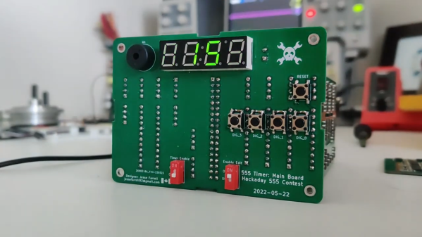
So why exactly did [Jesse Farrell] manage to do essentially the same thing using a whopping 276 555s? Easy — because why not? Originally started as an entry in the latest iteration of our 555 Contest, [Jesse]’s goal was simple — build a functional timer with a digital display using nothing but 555s and the necessary passives. He ended up needing a few transistors and diodes to pull it off, but that’s a minor concession when you consider how many chips he replaced with 555s, including counters, decoders, multiplexers, and display drivers. All these chips were built up from basic logic gates, a latch, and a flip-flop, all made from one or more 555s, or variants like the 556 or 558.

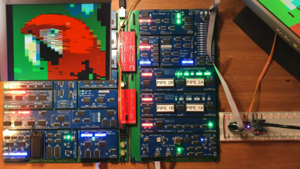
As one can imagine, 276 chips take a lot of real estate, and it took eleven PCBs to complete the timer. A main board acts as the timer’s control panel as well as serving as a motherboard for ten other cards, each devoted to a different block of functions. It’s all neat and tidy, and very well-executed, which is in keeping with the excellent documentation [Jesse] produced. The whole thing is wonderfully, needlessly complex, and we couldn’t be more tickled to feature it.

Continue reading “Should’ve Used A 555 — Or 276 Of Them”

VGA From Scratch On A Homebrew 8-bit Computer

[James Sharman] has built an impressive 8-bit homebrew computer. Based on TTL logic chips, it has a pipelined design which makes it capable of Commodore-level computing, but [James] hasn’t quite finished everything yet. While it is currently built on its own custom PCB, it has a limiting LCD display which isn’t up to the standards of the rest of the build. To resolve this issue, he decided to implement VGA from scratch.

This isn’t a bit-bang VGA implementation, either. He plans for full resolution (640×480) which will push the limits of his hardware. He also sets goals of a 24-bit DAC which will allow for millions of colors, the ability to use sprites, and hardware scrolling. Since he’s doing all of this from scratch, the plan is to keep it as simple as possible and make gradual improvements to the build as he goes. To that end, the first iteration uses a single latching chip with some other passive components. After adding some code to the CPU to support the new video style, [James] is able to display an image on his monitor.

While the image of the parrot he’s displaying isn’t exactly perfect yet, it’s a great start for his build and he does plan to make improvements to it in future videos. We’d say he’s well on his way to reproducing a full 8-bit retrocomputer. Although VGA is long outdated for modern computers, the standard is straightforward to implement and limited versions can even be done with very small microcontrollers.

Thanks to [BaldPower] for the tip!

Continue reading “VGA From Scratch On A Homebrew 8-bit Computer”

Project Egress: Two Ways To Latch The Hatch

With July slipping away and the deadline approaching, the Project Egress builds are pouring in now. And we’re starting to see more diversity in the choice of materials and methods for the parts being made, like these two latches made with very different methods by two different makers.

For the uninitiated, Project Egress is a celebration of both the 50th anniversary of Apollo 11 and the rise of the maker movement. Spearheaded by [Adam Savage], the idea is to engage 44 prominent makers to build individual parts from the Unified Crew Hatch (UCH) from the Apollo Command Module. The parts will be used to create a replica of this incredibly complex artifact, which will be assembled by [Adam] before a live audience at the National Air and Space Museum next week.

Both [Joel] from the “3D Printing Nerd” channel and [Bill Doran] from “Punished Props Academy” got the nod for one of the 15 latches needed, and both played to their respective strengths. [Joel]’s latch was executed in PLA on a Prusa I3 printer. [Bill] went a different route for his latch. He used a Form 2 SLA printer to print the parts, but used them only to make silicone molds. He then cast the parts from urethane resin, which should prove much stronger than the original SLA prints. We suspect the ability to quickly cast more latches could prove handy if any of the other latch makers should fail to deliver.

The latches [Joel] and [Bill] made joins the other parts, like the wooden latch being made by [Fran Blanche] and the hatch handle [Paul] cast in aluminum. We’re looking forward to more part builds, as well as the final assembly.

Continue reading “Project Egress: Two Ways To Latch The Hatch”

Project Egress: [Fran] Makes A Latch

[Fran Blanche] is on the team of elite hackers that has been offered a chance to contribute to [Adam Savage]’s Project Egress, a celebration of the engineering that got humanity to the Moon 50 years ago this month. By the luck of the draw, she landed a great assignment: building a replica of one of the fifteen latches that kept the Apollo Command Module hatch dogged down against the vacuum of space, and she’s doing a great job documenting her build with some interesting videos.

The first video below is mostly her talking through her design process, materials choices, and ideas about fabricating the somewhat intricate pieces of the latch. All 44 makers involved in the project get to choose what materials and methods they’ll use to make their parts, and [Fran] decided to use wood. Her first inclination was to use oak and brass, a nice combination with an 80s vibe, but in the second video, which covers more of the initial fabrication, she explains her switch to walnut. Unfortunately, the only CNC option she has is a Shaper Origin, which presents some difficulties; the handheld tool requires some complicated fixturing to safely machine the small parts needed, and its inability to read STL files means that [Fran] is stuck with a complicated software toolchain to drive the tool.

There are more videos to come as [Fran] gets further into the build, and we’re looking forward to seeing how her part and the rest of the makers’ builds come out.

Continue reading “Project Egress: [Fran] Makes A Latch”

Help Solve The Single-Transistor Latch Mystery

If you’ve spent any time on hackaday.io, you may have noticed that more than a few denizens of the site are fans of “alternative” electronic logic. Aiming to create digital circuits from such things as relays, vacuum tubes, discrete transistors, and occasionally diodes, they come up with designs that use these components in either antiquated or occasionally new and unexpected ways. This is exactly what [Mark Sherman] has done with his latest project, a single-transistor latch.

If you think every design has to compete with cutting-edge integrated circuits, or even must have an immediate practical application, you might as well stop reading now — and to play on the famous Louis Armstrong quip about jazz, if you have to ask why someone would do such a thing, you’ll never know.

Given that you’ve come this far, you’ll appreciate what [Mark] has come up with. It’s semi-well-known that the collector-emitter junction of a bipolar junction transistor (BJT) can exhibit a negative resistance characteristic when reverse-biased into avalanche breakdown. It’s this principle that allows a single BJT to be used as an ultra-simple LED flasher. [Mark] took this concept and ran with it, creating a single-transistor latch that can store one bit of information. As a bonus — or is it a requirement? — the transistor also drives an LED, so that you can visualize the state. We’ve seen a one-transistor flip-flop before, but that one also required diodes and an AC bias supply. In this new device, none of this is necessary, so it’s a step up according to the unwritten, unspoken, and generally agreed upon rules of the game.

In true hacker fashion, [Mark] came up with a working device without fully understanding exactly how it works.  We, too, are a little mystified at first glance. So, [Mark] is asking for your help in replicating and/or analyzing the circuit. He explains what he has found so far in the video after the break, but the main questions seem to revolve around why the base resistor is required, and why it works with 2N4401s but not 2N2222s.

So, Hackaday, what’s going on here? Sound off in the comments below.

Continue reading “Help Solve The Single-Transistor Latch Mystery”

Blacksmith Elevates The Craft With This Fabulous Strongbox

For most of human industrial history, the blacksmith was the indispensable artisan. He could fashion almost anything needed, from a simple hand tool to a mechanism as complex as a rifle. Starting with the most basic materials, a hot forge, and a few tools that he invariably made himself, the blacksmith was a marvel of fabrication.

If you have any doubt how refined the blacksmith’s craft can be, feast your eyes on [Seth Gould]’s masterpiece of metalwork. Simply called “Coffer”, [Seth] spent two years crafting the strongbox from iron, steel, and brass. The beautifully filmed video below shows snippets of the making, but we could easily watch a feature-length film detailing every aspect of the build. The box is modeled after the strongboxes built for the rich between the 17th and 19th centuries, which tended to favor complex locking mechanisms that provided a measure of security by obfuscation. At the end of the video below, [Seth] goes through the steps needed to unlock the chest, each of which is filled with satisfying clicks and clunks as the mechanism progresses toward unlocking. The final reveal is stunning, and shows how much can be accomplished with a forge, some files, and a whole lot of talent.

If you’ve never explored the blacksmith’s art before, now’s the time. You can even get started easily at home; [Bil Herd] will show you how.

Continue reading “Blacksmith Elevates The Craft With This Fabulous Strongbox”

Vintage Programmer Gets Modern Chip Adapter

While trying to revive a Donkey Kong Jr arcade board, [Jelmer Bruijn] found himself in the market for an EPROM programmer and became the proud owner of a 1990’s era Dataman S4. Despite its age, it’s a fairly nice tool which allows you to read and write a laundry list of different EPROM types, all without being tied to a computer. The only catch is that a few types of chips need an adapter to work in the Dataman S4, some of which are unsurprisingly no longer available.

After some above and beyond support from the current crew at Dataman set him on the right track, [Jelmer] decided to try his hand at reverse engineering how the old adapters worked so he could build his own. His ultimate goal was to read 40 pin EPROMs on the 32 pin Dataman S4, but in the end he says the information he gathered should be applicable for building other adapters if you ever find yourself in need of such things.

As you might expect, there’s a bit more to the project than a simple pin adapter. [Jelmer] assumed some kind of shift register or latching arrangement would be required to make up for the shortage of pins on the Dataman S4’s ZIF socket. It was just a matter of figuring out how it all went together.

Luckily, [Jelmer] found that the programmer would happily attempt to perform operations on a 16 bit EPROM even though no adapter was physically present. This gave him a chance to probe around with a logic analyzer to figure out what it was trying to accomplish. The trick turned out to be splitting the 16 bit bus into two 8 bit buses which are requested sequentially.

With careful observation, close studying of 16 bit chip datasheets, and much brow furrowing, he was eventually able to come up a design that used five 74xx573 latches and put a schematic together in Eagle. There were a few kinks to iron out when the boards finally arrived, but ultimately the design worked on the first try. [Jelmer] says the same technique should work for 42 pin EPROMs, but as Dataman still actually sell adapters for those he decided not to supply schematics for it.

[Jelmer] tells us that he was inspired to send this success story our way after reading how our very own [Elliot Williams] took the long away around to erase a couple UV EPROMs recently While this isn’t the first time we’ve seen somebody have to hack support for 16 bit EPROMs into their programmer, it’s good to see that the manufacturer at least had the customer’s back in this case.