Ask Hackaday: Arduino In Consumer Products

Speak with those who consider themselves hardcore engineers and you might hear “Arduinos are for noobs” or some other similar nonsense. These naysayers see the platform as a simplified, overpriced, and over-hyped tool that lets you blink a few LEDs or maybe even read a sensor or two. They might say that Arduino is great for high school projects and EE wannabes tinkering in their garage, but REAL engineering is done with ARM, x86 or PICs. Guess what? There are Arduino compatible boards built around all three of those architectures. Below you can see but three examples in the DUE, Galileo, and Fubarino SD boards.

This attitude towards Arduino exists mainly out of ignorance. So let’s break down a few myths and preconceived biases that might still be lurking amongst some EEs and then talk about Arduino’s ability to move past the makers.

Arduino is NOT the Uno

When some hear “Arduino”, they think of that little blue board that you can plug a 9v battery into and start making stuff. While this is technically true, there’s a lot more to it than that.

  1. An Arduino Uno is just an AVR development board. AVRs are similar to PICs. When someones says “I used a PIC as the main processor”, does that mean they stuck the entire PIC development board into their project? Of course not. It’s the same with Arduino (in most cases), and design is done the same way as with any other microcontroller –
    • Use the development board to make, create and debug.
    • When ready, move the processor to your dedicated board.
  2. What makes an Arduino an “Arduino” and not just an AVR is the bootloader. Thus:
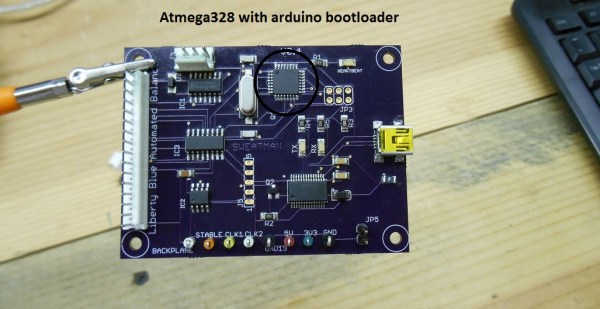
    • An Atmega328P is an AVR processor.
    • An Atmega328P with the Arduino bootloader is an Arduino.
  3. The bootloader allows you to program the AVR with the Arduino IDE. If you remove the bootloader from the AVR, you now have an AVR development board that can be programmed with AVR Studio using your preferred language.

There Is No Special Arduino Language

Arduino "blink" sketch should run on any Arduino compatible board.
Arduino “blink” sketch should run on any Arduino compatible board.

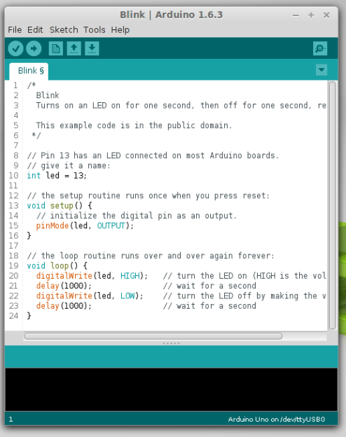
Yes, I know they call them sketches, which is silly. But the fact is it’s just c++. The same c++ you’d use to program your PIC. The bootloader allows the IDE to call functions, making it easy to code and giving Arduino its reputation of being easy to work with. But don’t let the “easy” fool you. They’re real c/c++ functions that get passed to a real c/c++ compiler. In fact, any c/c++ construct will work in the Arduino IDE. With that said – if there is any negative attribute to Arduino, it is the IDE. It’s simple and there is no debugger.

The strength comes in the standardization of the platform. You can adapt the Arduino standard to a board you have made and that adaptation should allow the myriad of libraries for Arduino to work with your new piece of hardware. This is a powerful benefit of the ecosystem. At the same time, this easy of getting things up and running has resulted in a lot of the negative associations discussed previously.

So there you have it. Arduino is no different from any other microcontroller, and is fully capable of being used in consumer products along side PICs, ARMs etc. To say otherwise is foolish.

What is the Virtue of Arduino in Consumer Products?

This is Ask Hackaday so you know there’s a question in the works. What is the virtue of Arduino in consumer products? Most electronics these days have a Device Firmware Upgrade (DFU) mode that allows the end user to upgrade the code, so Arduino doesn’t have a leg up there. One might argue that using Arduino means the code is Open Source and therefore ripe for community improvements but closed-source binaries can still be distributed for the platform. Yet there are many products out there that have managed to unlock the “community multiplier” that comes from releasing the code and inviting improvements.

What do you think the benefits of building consumer goods around Arduino are, what will the future look like, and how will we get there? Leave your thoughts below!

Trick Google Used Hides Secret Messages On LCD Screens

[Travis] didn’t get picked to go to Google I/O this year, but he did have some I/O inspired fun after the fact. His friends who did go told him about specially modified LCD screens Google had scattered around the event. The screens showed normal show information when viewed with the naked eye. When viewed through a special transparent badge included with the I/O swag though, a URL for Google’s scavenger hunt would magically appear. [Travis] was intrigued by the effect, and became hell-bent on reproducing it himself.

[dual-lcd-3
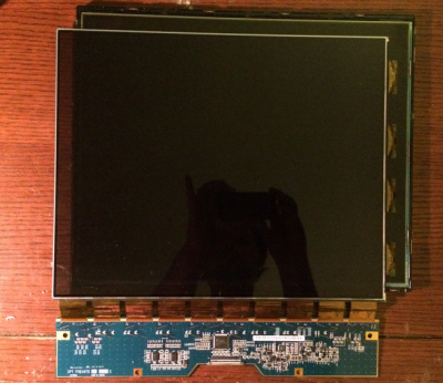
Travis] figured out the transparent badge was actually a polarizing filter. Every standard LCD has two of them, usually bonded to the glass of the LCD itself. If you remove the filters from a LCD, you’ll get a prime view of the backlight – unless you’re wearing polarizing glasses of course. Google’s monitors didn’t have that effect though. They showed a full color display, with a second full color hidden display only visible through the polarizer

It only took a bit of three-dimensional thinking for him to figure out Google’s trick. There are actually two LCDs used in the display. The first is a standard LCD with backlight. The trick is to strip the polarizing film off a second LCD and place it in front of the first. The second LCD will be invisible to anyone – without the polarizer.

[Travis] quickly set about replicating the display using several obsolete VGA LCDs. He quickly found that the hard part was peeling the polarizing plastic from the thin glass LCD sandwich. Several LCDs gave up their lives in the effort, but in the end [Travis] was successful. He made everything fit in one case by using a thin LED backlight in a case designed for a monitor with a Cold Cathode Fluorescent Lamp (CCFL).  The result looks exactly like a standard LCD – that is, until viewed through a polarizing filter. Click past the break to see the hidden message LCD in action!

Continue reading “Trick Google Used Hides Secret Messages On LCD Screens”

Controlling Quadcopters With Wireless Mouse Dongles

Last week we gave away a few Crazyflie 2.0 quadcopters to some cool Hackaday Prize entries. This quadcopter ships with the intention of being controlled by your smartphone. But it can also be controlled by a PC with USB dongle and an nRF24LU1+ SOC. [ajlitt] didn’t figure out he wanted the USB dongle (the Crazyradio) that can control this quad until after he used his gift code to claim his Crazyflie quad. No matter; the dongles for Logitech wireless keyboards and mice use the same radio as the Crazyflie and can be modded to make this quad fly.

The board inside the Logitech unifying receiver is a simple affair, with some pads for the USB connector, a crystal, the nRF24LU1+ radio module, and a few passives. To get this radio chip working with his computer, [ajlitt] simply needed to break out the SPI pins and wire everything to a Bus Pirate.

Getting the Crazyradio firmware onto this proved to be a little harder than soldering some magnet wire onto a few pins. The chip was first flashed without a bootloader, a full image with the bootloader was found, after wrangling a single byte into place, [ajlitt] had a working Crazyflie radio made from a wireless mouse dongle. The range isn’t great  – only 30 feet or so, or about as far as you would expect a wireless mouse to work. Excellent work, even if [ajlitt] is temporarily without a mouse.

The Crazyflie 2.0 is available from the Hackaday Store, along with the add-ons if you don’t want to hack your own.

Billy Club Says No

Billy Club Texts Your Mother If You Hit Someone

Mama, just killed hit a man, Put a gun against his head, Pulled my trigger, now he’s dead.
Mama, life had just begun, But now I’ve gone and thrown it all away…

This latest piece of half-art / half-prototype from one of our favorite hacker-artists [vtol] is a billy club equipped with a GSM-module. It automatically sends an SMS to your mother with the text: “Mom, I hit a man.” He calls it the Antenna:

The idea of the project is to create a device which strictly controls the cruelty of police. As all the standard methods of control are ineffective, this project suggests the maternity as the last stronghold of human kindness and responsibility.

An Arduino is equipped with a piezo sensor to detect impact, and a GSM shield takes care of the texting. It’s an interesting concept, similar to requiring police officers to wear body cameras. You can debate the practicality, but we’re always interested in hearing about weapons monitoring tech concepts. One of our favorites has always been the DNA gun from (Judge) Dredd. Did you know there was an Internet Movie Firearms Database? But we digress, check out [vtol’s] demo video:

Continue reading “Billy Club Texts Your Mother If You Hit Someone”

Carbon fiber weaving robot!

Hackaday Prize Entry: Weaving Carbon Fiber With Industrial Robots

Oh to have a 6-axis robot arm to play with… For [Basia Dzaman’s] final graduation project for School of Form, she designed and 3D printed an end effect tool for an industrial KUKA robot — for weaving carbon fiber.

Through an iterative design process, she developed many prototypes of the tool until the one you see above. It’s capable of holding a Dremel multi tool which can be used to drill into a work surface for installing pegs which make up the custom weaving jig. The pegs (nails) are then installed by hand so that the robot can thread carbon fiber — fed through an epoxy bath as it is dispensed — onto the jig. In the example, she shows a traditional Polish handcraft called Snutki (a type of stitching), wrapping the carbon fiber in patterns around the pegs. Once the epoxy cures, a strong structure can be removed.

Remember the 6-axis robot that can 3D print in metal, and is currently working on 3D printing a bridge? [Basia’s] design could do similar things, for a completely different industry. You can check out [Basia]’s video for the project below.

The 2015 Hackaday Prize is sponsored by:

Continue reading “Hackaday Prize Entry: Weaving Carbon Fiber With Industrial Robots”

Using A TeensyLC To Emulate The XBOX 360 Controller

After the release of Mortal Kombat X, [Zachery’s] gaming group wanted to branch out into the fighter genre. They quickly learned that in order to maximize their experience, they would need a better controller than a standard gamepad. A keyboard wasn’t going to cut it either. They wanted a fight stick. These are large controllers that look very much like arcade fighting controls and include a joystick and large buttons. [Zachery’s] group decided to build their own fight stick for use with a PC.

[Zachery] based his build around the TeensyLC, which is a 32 bit development board with an ARM processor. It’s also compatible with Arduino. The original version of his project setup the controller as a HID, essentially emulating a keyboard. This worked for a while until they ran into compatibility issues with some games. [Zachery] learned that his controller was compatible with DirectInput, which has been deprecated. The new thing is Xinput, and it was going to require more work.

Using Xinput meant that [Zachery] could no longer use the generic Microsoft HID driver. Rather than write his own drivers, he decided to emulate the XBOX 360 controller. When the fight stick is plugged into the computer, it shows up as an XBOX 360 controller and Windows easily installs the pre-built driver. To perform the emulation, [Zachery] first had to set the VID and PID of the device to be identical to the XBOX controller. This is what allows the Microsoft driver to recognize the device.

Next, the device descriptor and configuration descriptor had to be added to the Teensy’s firmware. The device descriptor includes information such as USB version, device class, protocol, etc. The configuration descriptor includes additional information about the device configuration. [Zachery] used Microsoft Message Analyzer to pull the configuration descriptor from a real XBOX 360 controller, then used the same data in his own custom controller.

[Zachery] programmed the TeensyLC using the Arduino IDE. He ran into some trouble here because the IDE did not include the correct device type for an Xinput device. [Zachery] had to edit the boards.txt file and add three lines of code in order to add a new hardware device to the IDE’s menu. Several other files also had to be modified to make sure the compiler knew what an Xinput device type was.  With all of that out of the way, [Zachery] was finally able to write the code for his controller.

Retrotechtacular: The J-57 Afterburner Engine

The J-57 afterburner engine appeared in many airplanes of notable make, including the F-101, -102, and -103. This USAF training film shows the parts of the J-57, explains the complex process by which the engine produces thrust, and describes some maintenance and troubleshooting procedures.

The name of this game is high performance. Precision thrust requires careful rigging of the engine’s fuel control linkage through a process called trimming. Here, the engine fuel control is adjusted with regard to several different RPM readings as prescribed in the manual.

One of the worst things that can happen to a J-57 is known as overtemping. This refers to high EGT, or exhaust gas temperature. If EGT is too high, the air-fuel ratio is not ideal. Troubleshooting a case of high EGT should begin with a check of the lines and the anti-icing valve. If the lines are good and the valve is closed, the instruments should be checked for accuracy. If they’re okay, then it’s time for a pre-trimming inspection.

In addition to EGT, engine performance is judged by RPM and PP7, the turbine discharge pressure. If RPM and PP7 are within spec and the EGT is still high, the engine must be pulled. It should be inspected for leaks and hot spots, and the seals should be examined thoroughly for cracks and burns. The cause for high EGT may be just one thing, or it could be several small problems. This film encourages the user to RTFM, which we think is great advice in general.

Continue reading “Retrotechtacular: The J-57 Afterburner Engine”