Looks Like A Pi Zero, Is Actually An ESP32 Development Board

ATMegaZero ESP32- S2, showing optional color-coded 40-pin header (top)

The ATMegaZero ESP32-S2 is currently being funded with a campaign on GroupGets, and it’s a microcontroller board modeled after the Raspberry Pi Zero’s form factor. That means instead of the embedded Linux system most of us know and love, it’s an ESP32-based development board with the same shape and 40-pin GPIO header as the Pi Zero. As a bonus, it has some neat features like a connector for inexpensive SSD1306 and SH1106-based OLED displays.

Being able to use existing accessories can go a long way towards easing a project’s creation, and leveraging that is one of the reasons for sharing the Pi Zero form factor. Ease of use is also one of the goals, so the boards will ship with CircuitPython (derived from MicroPython), and can also be used with the Arduino IDE.

If a microcontroller board using the Pi Zero form factor looks a bit familiar, you might be remembering the original ATMegaZero which was based on the Atmel ATMega32U4, but to get wireless communications one needed to attach a separate ESP8266 module. This newer board keeps the ATMegaZero name and footprint, but now uses the Espressif ESP32-S2 to provide all the necessary functions.

CircuitPython has been a feature in a wide variety of projects and hacks we’ve seen here at Hackaday, and it’s a fine way to make a microcontroller board easy to use right out of the box.

This DIY Split-Flap Display Does Both Time And Weather

With little more than four economical stepper motors, a Raspberry Pi Zero, and a 3D printer, [Thomas Barlow] made himself an awfully slick Smart Flip Clock that can display not only the time, but also weather data as well. This is done by adding a few extra graphics to some of the split-flaps, so numbers can also be used to indicate temperature and weather conditions succinctly. Displaying the time has to do without a colon (so 5:18 displays as 518), but being able to show temperature and weather conditions more than makes up for it.

32 degrees and a mix of sun and cloud

According to the project’s GitHub repository, it looks as though each split-flap has thirteen unique positions. The first ten are for numerals 0 through 9, and the rest are either blank, or used to make up a few different weather icons with different combinations. A Python script runs on the Raspberry Pi and retrieves weather data from OpenWeather, and the GPIO header drives the display via four geared stepper motors and driver boards. The rest of the hardware is 3D printed, and [Thomas] helpfully provides CAD models in STEP format alongside the STL files.

The basic design of a split-flap display is really quite versatile, and enterprising hackers have been putting delightful new twists on them for years. There has been a split-flap display used as a kind of flip-book animation, and we’ve also had the pleasure of seeing an entire Tarot deck used for esoteric, automated readings.

Faux Stained Glass Effect, With 3D Printing And Epoxy

Like the looks of stained glass, but not the amount of work, skill, and materials involved? Well, [Northern Geometry] shows how to sidestep all that nonsense and use a 3D printed frame, epoxy, and some alcohol-based inks to create a pretty good fake stained-glass effect piece of art.

A smooth polypropylene board is the key to a glassy smooth back.

[Northern Geometry] has played with this idea before, but shares some refinements and tips on getting the best results. One suggestion is to begin by securely taping the 3D printed frame to a smooth polypropylene board as a backer. Giving the cured resin a smooth surface is important to get the right look, and since resin will not bond to the polypropylene, it can be used as a backer to get that done.

Once the frame is mounted, pour a small amount of epoxy into each cavity and ensure it gets into every corner, then let it cure. The thin bottom layer of resin will seal things as well as create a glassy-smooth backing that is the perfect foundation for finishing the piece with colored resin as needed.

Once that is done, and everything has had plenty of time to cure fully, just pop the piece off the board. Check it out in the video embedded below, where [Northern Geometry] shows the process from start to finish.

Continue reading “Faux Stained Glass Effect, With 3D Printing And Epoxy”

Art of 3D printer in the middle of printing a Hackaday Jolly Wrencher logo

What To Expect From 3D Scanning, And How To Work With It

3D scanning and 3D printing may sound like a natural match for one another, but they don’t always play together as easily and nicely as one would hope. I’ll explain what one can expect by highlighting three use cases the average hacker encounters, and how well they do (or don’t) work. With this, you’ll have a better idea of how 3D scanning can meet your part design and 3D printing needs.

How Well Some Things (Don’t) Work

Most 3D printing enthusiasts sooner or later become interested in whether 3D scanning can make their lives and projects easier. Here are a three different intersections of 3D scanning, 3D printing, and CAD along with a few words on how well each can be expected to work.

Goal Examples and Details Does it work?
Use scans to make copies of an object.
  • 3D scan something, then 3D print copies.
  • Objects might be functional things like fixtures or appliance parts, or artistic objects like sculptures.
Mostly yes, but depends on the object
Make a CAD model from a source object.
  • The goal is a 1:1 model, for part engineering purposes.
  • Use 3D scanning instead of creating the object in CAD.
Not Really
Digitize inconvenient or troublesome shapes.
  • Obtain an accurate model of complex shapes that can’t easily be measured or modeled any other way.
  • Examples: dashboards, sculptures, large objects, objects that are attached to something else or can’t be easily moved, body parts like heads or faces, and objects with many curves.
  • Useful to make sure a 3D printed object will fit into or on something else.
  • Creating a CAD model of a part for engineering purposes is not the goal.
Yes, but it depends

In all of these cases, one wants a 3D model of an object, and that’s exactly what 3D scanning creates, so what’s the problem? The problem is that not all 3D models are alike and useful for the same things.

Continue reading “What To Expect From 3D Scanning, And How To Work With It”

DIY Wireless Serial Adapter Speaks (True) RS-232

There is a gotcha lurking in wait for hackers who look at a piece of equipment, see a port labeled “Serial / RS-232”, and start to get ideas. The issue is the fact that the older the equipment, the more likely it is to be a bit old-fashioned about how it expects to speak RS-232. Vintage electronics may expect the serial data to be at bipolar voltage levels that are higher than what the typical microcontroller is used to slinging, and that was the situation [g3gg0] faced with some vintage benchtop equipment. Rather than deal with cables and wired adapters, [g3gg0] decided to design a wireless adapter with WiFi and Bluetooth on one end, and true RS-232 on the other.

The adapter features an ESP32 and is attached to a DB-9 plug, so it’s nice and small. It uses the ST3232 chip to communicate at 3 V logic levels on the microcontroller side, supports bipolar logic up to +/-13 V on the vintage hardware side, and a rudimentary web interface allows setting hardware parameters like baud rate. The nice thing about the ST3232 transceiver is that it is not only small, but can work from a 3 V supply with only four 0.1 uF capacitors needed for the internal charge pumps.

As for actually using the adapter, [g3gg0] says that the adapter’s serial port is exposed over TCP on port 23 (Telnet) which is supported by some programs and hardware. Alternately, one can connect an ESP32 to one’s computer over USB, and run firmware that bridges any serial data directly to the adapter on the other end.

Design files including schematic, bill of materials, and PCB design are shared online, and you can see a brief tour of the adapter in the video, embedded below.

Continue reading “DIY Wireless Serial Adapter Speaks (True) RS-232”

E.T. Video Game Gets Re-Imagined In 10 Lines Of BASIC

Most people would recognize E.T. The Extra-Terrestrial for the Atari 2600 by its reputation as one of the worst video games of all time. We’ll have more to say about that in a moment, but E.T. was nevertheless chosen as the inspiration behind [Martin Fitzpatrick]’s re-imagining of the game in ten lines of BASIC code for a contest that encourages and celebrates games written in ten lines of BASIC, or less.

Ten lines of BASIC is a big limitation, even when getting clever by stacking multiple statements into a single line, so [Martin]’s game has a much narrower scope than the original Atari 2600 version. Still, the core elements are present: E.T. must find and gather all the parts of the phone in order to contact his ship, after which he must meet the ship in time to escape. All the while, FBI agents attempt to interfere. The game was written in SAM BASIC, used by the SAM CoupĂ©, a British Z80-based home computer from the late 80s with an emulator available for download.

Now, for lovers of “um, actually” topics, do we have a treat for you! Let’s take this opportunity to review a few things about E.T. The Extra-Terrestrial. That it was a commercial flop is no doubt, but the game itself is often badly misunderstood. Way back in 2013 we covered an extraordinary effort to patch improvements into the binary for the 2600 game, and in the process there’s a compelling case made that the game was in many ways far ahead of its time, and actually quite significant in terms of game design. You can jump right in on an analysis of the hate the game receives, and while reading that it’s helpful to keep in mind that In 1982, many of its peers were games like Space Invaders, with self-evident gameplay that simply looped endlessly.

LED Brightness Adjustment Uses Itself As Sensor

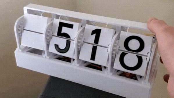
This is a story about a successful system that nevertheless failed to make the cut. An experimental LED brightness adjustment is something [Mitxela] explored in a project for a high-precision clock; one that shows time down to the nearest millisecond, and won’t flicker or otherwise look weird when photographed with a high-speed camera. To pull this off means reinventing many things about a clock display, including how to handle brightness adjustment elegantly. Now, to be clear, the brightness adjustment idea described here is something that did not end up being used, but it’s interesting enough that [Mitxela] wrote it up and we’re very glad he did.

The idea was to have a smooth and seamless automatic brightness adjustment, ideally with no added components. Since LEDs can be used as light sensors, [Mitxela] saw an opportunity to use elements of the clock displays themselves as sensors. This is how it works: a charge in the p-n junction that makes up an LED will decay at a rate proportional to the amount of light hitting the junction. By measuring the speed of this decay, it’s therefore possible to tell how much light is hitting the LED. It’s effective and elegant, but there are a few practical issues to deal with.

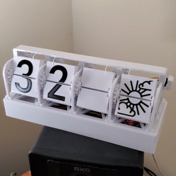
The first failed idea was to employ as sensors the unused decimal points in the seven-segment LED modules, but that turned out to have issues. One was the common-cathode wiring of the display modules; this makes them very convenient to drive as displays, but made using the decimal point as a light sensor impractical. The other issue was that the built-in diffuser that makes the displays easier to read absorbs a lot of ambient light. A much better option was to use the LEDs in the colon separators between digits, since they’re independent. Naturally they still have to light up in addition to being used as sensors, but [Mitxela] made a successful prototype by performing the necessary measurements in between the LEDs being driven by PWM.

Despite how clever and efficient the solution was, in the end what sank it was the fact that the LEDs just don’t do a very good job of sensing ambient light for this purpose. The LEDs are simply too directional. Even after sanding away the top (lens) part of the LEDs, they still had a very narrow field of view. As [Mitxela] describes it, tilting the clock towards the ceiling could send it to full brightness, and the shadow of one’s head falling across the clock would plummet it into “night mode” dimness. In short, it responded to what was directly in front of it, rather than the ambient light level as a whole.

It’s a reminder that sometimes a solution simply won’t tick all the right boxes, and it can happen for unexpected reasons. Still, LEDs are versatile things. Not only can they sense light, but as the name implies they’re also diodes. As diodes can be used as temperature sensors that means LEDs can as well.