We can say one thing for [bitluni]: the BOMs for his projects, like this ESP32 AM radio transmitter, are always on the low side. That’s because he leverages software to do jobs traditionally accomplished with hardware, always with instructive results.
In this case, the job at hand is creating an RF oscillator in the broadcast AM band and modulating some audio onto it. From his previous experience using an ESP32 to watch video on an oscilloscope, [bitluni] knew that the microcontroller’s DACs were up to the task of producing an 800-kHz signal, and he managed to produce a more-or-less sine wave carrier with some clever code. His sketch takes data from a header file, modulates it onto the carrier, and sends it out over the ether using a short stub of wire for an antenna. The range is severely limited, but for what it is, it gets the job done and shows the basics. And as a bonus, [bitluni] included a bit of JavaScript that turns an audio file into a header file that’s ready to go out over the airwaves for all your trolling needs.
If you’re looking for a little more range for your low power transmitter and you’re a licensed amateur operator, you might want to explore the world of QRP radio.
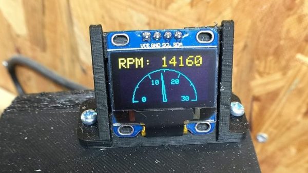
With CNC machines, getting the best results depends on knowing how fast your tool is moving relative to the workpiece. But entry-level CNC routers don’t often include a spindle tachometer, forcing the operator to basically guess at the speed. This DIY optical spindle tach aims to fix that, and has a few nice construction tips to boot.
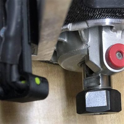
The CNC router in question is the popular Sienci, and the 3D-printed brackets for the photodiode and LED are somewhat specific for that machine. But [tmbarbour] has included STL files in his exhaustively detailed write-up, so modifying them to fit another machine should be easy. The sensor hangs down just far enough to watch a reflector on one of the flats of the collet nut; we’d worry about the reflector surviving tool changes, but it’s just a piece of shiny tape that’s easily replaced. The sensor feeds into a DIO pin on a Nano, and a small OLED display shows a digital readout along with an analog gauge. The display update speed is decent — not too laggy. Impressive build overall, and we like the idea of using a piece of PLA filament as a rivet to hold the diodes into the sensor arm.
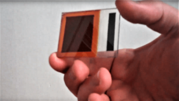
The idea of making your own semiconductors from scratch would be more attractive if it weren’t for the expensive equipment and noxious chemicals required for silicon fabrication. But simple semiconductors can be cooked up at home without anything fancy, and they can actually yield pretty good results.
Granted, [Simplifier] has been working on the method detailed in the video below for about a year, and a look at his post on copper oxide thin-film solar cells reveals a meticulous approach to optimize everything. He started with regular window glass, heated over a propane burner and sprayed with a tin oxide solution to make it conductive while remaining transparent. The N-type layer was sprayed on next in the form of zinc oxide doped with magnesium. Copper oxide, the P-type layer, was electroplated on next, followed by a quick dip in copper sulfide to act as another transparent conductor. A conductive compound of sodium silicate and graphite was layered on the back to form the electrical contacts. The cell worked pretty well — 525 mV open circuit voltage and 6.5 mA short-circuit current. Not bad for home brewed.
If you want to replicate [Simplifier]’s methods, you’ll find his ample documentation of his site. Of course, if you yearn for DIY silicon semiconductors, there’s a fab for that, too.
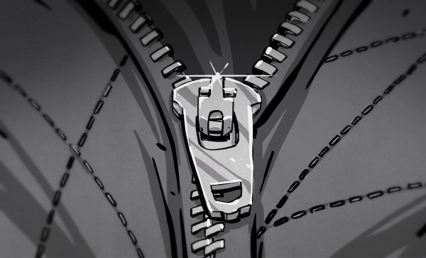
Look around yourself right now and chances are pretty good that you’ll quickly lay eyes on a zipper. Zippers are incredibly commonplace artifacts, a commodity item produced by the mile that we rarely give a second thought to until they break or get stuck. But zippers are a fairly modern convenience, and the story of their invention is one that shows even the best ideas can be delayed by overly complicated designs and lack of a practical method for manufacturing.
Try and Try Again
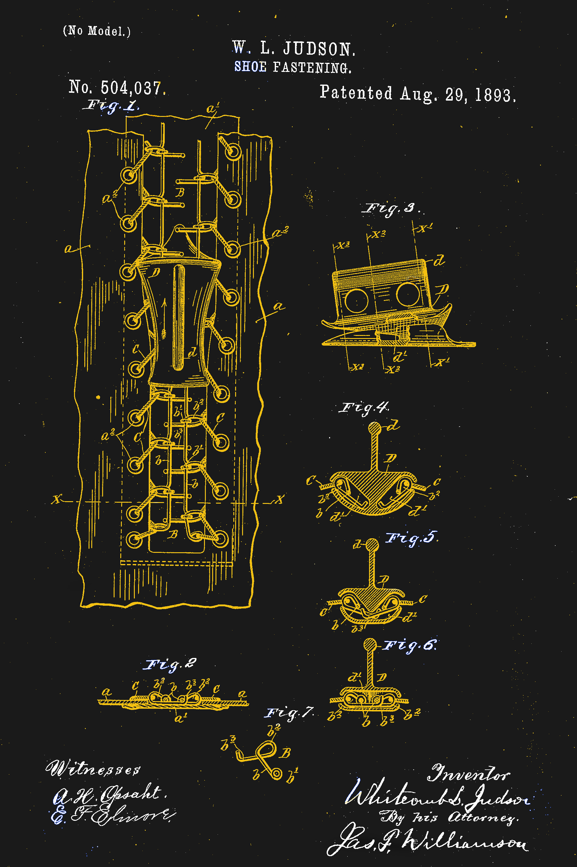
US Patent #504,307. One of the many iterations of Judson’s design. Like the others, it didn’t work.
Ideas for fasteners to replace buttons and laces have been kicking around since the mid-19th century. The first patent for a zipper-like fastener was issued to Elias Howe, inventor of the sewing machine. Though he was no slouch at engineering intricate mechanisms, Howe was never able to make his “Automatic, Continuous Clothing Closure” a workable product, and Howe shifted his inventive energies to other projects.
The world would wait another forty years for further development of a hookless fastener, when a Chicago-born inventor of little prior success named Whitcomb Judson began work on a “Clasp Locker or Unlocker.” Intended for the shoe and boot market, Judson’s device has all the recognizable parts of a modern zipper — rows of interlocking teeth with a slide mechanism to mesh and unmesh the two sides. The device was debuted at the Chicago World’s Fair in 1893 and was met with almost no commercial interest.
Judson went through several iterations of designs for his clasp locker, looking for the right combination of ideas that would result in a workable fastener that was easy enough to manufacture profitably. He lined up backers, formed a company, and marketed various versions of his improved products. But everything he tried seemed to have one or more serious drawbacks. When his fasteners were used in shoes, unexpected failure was a mere inconvenience. If a fastener on a lady’s dress opened unexpectedly, it could have been a social catastrophe. Coupled with a price tag that was exorbitantly high to cover the manual labor needed to assemble them, almost every version of Judson’s invention flopped.
It would take another decade, a change of company name, a cross-country move, and the hiring of a bright young engineer before the world would have what we would recognize as the first modern zipper. Judson hired Gideon Sundback in 1901, and by 1913 he was head designer at the Fastener Manufacturing and Machine Company, newly relocated to Meadville, Pennsylvania after a stop in Hoboken, New Jersey. Sundback’s design called for rows of identical teeth with cups on the underside and nibs on the upper, set on fabric tapes. A slide with a Y-shaped channel bent the tapes to open the gap between teeth, allowing the cups to nest on the nibs and mesh the teeth together strongly.
Sundback’s design had significant advantages over any of Judson’s attempts. First, it worked, and it was reliable enough to start quickly making inroads into fashionable apparel beyond its initial marketing toward more utilitarian products like tobacco pouches. Secondly, and perhaps more importantly, Sundback invented machinery that could make hundreds of feet of the fasteners in a day. This gave the invention an economy of scale that none of Judson’s fasteners could ever have achieved.
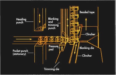
The machinery that Sundback invented to make his “Separable Fastener” has been much improved since the early 1900s, but the current process still looks similar, at least for metal zippers. Stringers, which are the fabric tapes with teeth attached, are formed in a continuous process by a multi-step punching and crimping machine. For metal stringers, a coil of flat metal is fed into a punch and die to form hollow scoops. The strip is then punched again to form a Y-shape around the scoop and cut it free from the web. The legs of the Y straddle the edge of the fabric tape, and a set of dies then crimps the legs to the tape. A modern zipper machine can make stringers at a rate of 2000 teeth per minute.
Plastic zippers are common these days, too, and manufacturing methods vary by zipper style. One method has the fabric tapes squeezed between the halves of a die while teeth are injection molded around the tape to form two parallel stringers. A sprue connected the stringers by the teeth breaks free after molding, and the completed stringers are assembled later.
Zippers have come a long way since Sundback’s first successful design, with manufacturing improvements that have eliminated many of the manual operations once required. Specialized zippers have made it from the depths of the oceans to the surface of the Moon, and chances are pretty good that if we ever get to Mars, one way or another, zippers will go with us.
Things rarely go well when humans mix with wildlife. The problems are exacerbated in the suburbs, where bears dine on bird feeders and garbage cans, raccoons take up residence in attics, and coyotes make off with the family cat. And in the suburbs, nuisance wildlife can be an intractable problem because the options for dealing with it are so limited.
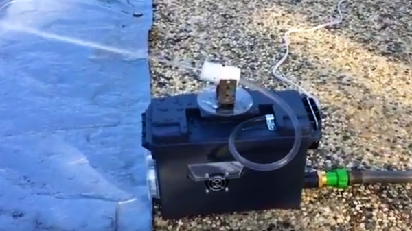
Not to be dissuaded in the battle to protect his roses, [dlf.myyta] built this motion-activated sentry gun to apply some watery aversion therapy to marauding deer. Shown in action below against a bipedal co-conspirator, the sentry gun has pretty much what you’d expect under the hood — Raspberry Pi, NoIR camera, a servo for aiming and a solenoid valve to control the water. OpenCV takes care of locating the intruders and swiveling the nozzle to center mass; since the deer are somewhat constrained by a fence, there’s no need to control the nozzle’s elevation. Everything is housed nicely in a plastic ammo can for portability and waterproofing. Any target that stands still for more than three seconds gets a hosing; we assume this is effective, but alas, no snuff films were provided.
We’re not sure if [dlf.myyta]’s code can discern friend from foe, and in this litigious world, hosing the neighbor’s kid could be a catastrophe. Perhaps version 2.0 can include image recognition for target verification.
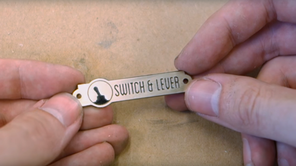
It’s the little touches that make a project, and a nice nameplate can really tie a retro build together. Such badges are easy enough to make with a CNC machine, but if you don’t have access to machine tools you can put chemistry to work for you with these acid-etched brass nameplates.
The etching method that [Switch and Lever] uses to get down to brass plaques will be intimately familiar to anyone who has etched a PCB before. Ferric chloride works as well on brass as it does on copper, and [Switch and Lever] does a good job explaining the chemistry of the etching process and offers some tips on making up etching solution from powdered ferric chloride. But the meat of the video below is the head-to-head test of three different masking methods.
The first method uses a laser printer and glossy paper ripped from a magazine to create a mask. The toner is transferred to the brass using an office laminator, and the paper removed with gentle rubbing before etching. For the other two candidates he uses a laser engraver to remove a mask of plain black spray paint in one case, or to convert special laser marking paint to a mask in the other.
We won’t spoil the surprise as to which gave the best results, but we think you’ll be pleased with how easy making classy nameplates can be. You can also use electrolytic methods for a deeper etch, but we think acid etching is a little more approachable for occasional use.
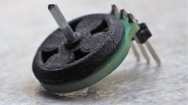
Mounting a motor on a PCB is nothing new, right? But how about making the PCB itself part of the motor? That’s what [Carl Bugeja] has done with his brushless DC motor in a PCB project, and we think it’s pretty cool.
Details on [Carl]’s Hackaday.io page are a bit sparse at this point, but we’ve been in contact with him and he filled us in a little. The PCB contains the stator of the BLDC and acts as a mechanical support for the rotor’s bearing. There are six spiral coils etched into the PCB, each with about 40 turns. The coils are distributed around the axis; connected in a wye configuration, they drive a 3D-printed rotor that has four magnets pressed into it. You can see a brief test in the video below; it seems to suffer from a little axial wobble due to the single bearing, but that could be handled with a hat board supporting an upper bearing.
We see a lot of potential in this design. [Carl] mentions that the lack of cores in the coil limit it to low-torque applications, but it seems feasible to bore out the center of the coils and press-fit a ferrite slug. Adding SMD Hall sensors to the board for feedback would be feasible, too — in fact, an entire ESC and motor on one PCB could be possible as well. [Carl] has promised to keep the project page updated, and we’re looking forward to more on this one.
 The CNC router in question is the popular Sienci, and the 3D-printed brackets for the photodiode and LED are somewhat specific for that machine. But [tmbarbour] has included STL files in his exhaustively detailed write-up, so modifying them to fit another machine should be easy. The sensor hangs down just far enough to watch a reflector on one of the flats of the collet nut; we’d worry about the reflector surviving tool changes, but it’s just a piece of shiny tape that’s easily replaced. The sensor feeds into a DIO pin on a Nano, and a small OLED display shows a digital readout along with an analog gauge. The display update speed is decent — not too laggy. Impressive build overall, and we like the idea of using a piece of PLA filament as a rivet to hold the diodes into the sensor arm.