Space elevators belong to that class of technology that we all want to see become a reality within our lifetimes, but deep-down doubt we’ll ever get to witness firsthand. Like cold fusion, or faster than light travel, we understand the principles that should make these concepts possible, but they’re so far beyond our technical understanding that they might as well be fantasy.
Except, maybe not. When Japan Aerospace Exploration Agency (JAXA) launches their seventh Kounotori H-II Transfer Vehicle towards the International Space Station, riding along with the experiments and supplies for the astronauts, will be a very special pair of CubeSats. They make up the world’s first practical test of space elevator technology, and with any luck, will be one of many small steps that precedes the giant leap which access to space at a fraction of the cost will be.
Of course, they won’t be testing a fully functional space elevator; even the most aggressive of timelines put us a few decades out from that. This will simply be a small scale test of some of the concepts that are central to building a space elevator, as we need to learn to crawl before we can walk. But even if we aren’t around to see the first practical space elevator make it to the top, at least we can say we were there on the ground floor.
French Defense Minister Florence Parly took a page out of Little Red Riding Hood when she recently called out a Russian satellite for having “big ears”. While she stopped short of giving any concrete details, it was a rare and not terribly veiled accusation that Russia is using their Luch-Olymp spacecraft to perform orbital espionage.
Luch satellite conceptual drawing from NASA
At a speech in Toulouse, Parly was quoted as saying: “It got close. A bit too close. So close that one really could believe that it was trying to capture our communications.” and “this little Stars Wars didn’t happen a long time ago in a galaxy far away. It happened a year ago, 36,000 kilometers above our heads.”
The target of this potential act of space piracy is the Athena-Fidus satellite, a joint venture between France and Italy to provide secure communication for the military and emergency services of both countries. Launched in 2014, it provides 3 Gbit/s throughput via the Ka-band for mobile receivers on the ground and in drones.
This isn’t the first time Russia’s Luch class of vehicles has been the subject of scrutiny. In 2015 it was reported that one such craft maneuvered to within 10 kilometers of the Intelsat 7 and Intelsat 901 geostationary communications satellites, prompting classified meetings at the United States Defense Department. As geostationary satellites orbit the Earth at 3.07 km/s, a 10 km approach is exceptionally dangerous. Even a slight miscalculation could cause an impact within seconds.
Could Stealth Satellites Be In Our Future?
Much to the chagrin of shadowy spy agencies everywhere, this sort of orbital cat and mouse is easily detectable from the ground. When spy planes became easy to detect using radar, the next step was to evade that detection. Are we on a path to satellites that are transparent to radar?
Gregory Charvat, author of Small and Short-Range Radar Systems and occasional contributor here at Hackaday, tells us that building a stealth satellite is no easy task. “Just like how we had to re-invent the aircraft to make the first stealth aircraft, to make a stealth satellite one would have to fundamentally re-invent the satellite as we know it today.”
Likening it to the immense cost and effort it took to develop stealth aircraft like the Lockheed F-117 Nighthawk, Gregory says developing a satellite which could hide from radar would likely be more trouble than it’s worth for most applications. Space is already hard enough. “Maintaining that special shape that reflects radar away from your aircraft and including all of these essential peripherals is a big challenge” Gregory says, which results in “compromise and high maintenance costs.”
Beyond attempting to eavesdrop on communications, military insiders say that these close passes by Luch satellites could also be “dry-runs” for anti-satellite operations; either by using a directed energy weapon to disable the target spacecraft, or simply running into it. With events like these, and the commitment by the United States to establish a Space Force in the coming years, efforts to militarize space seem to be on the rise.
The phrase “Go big or go home” is clearly not lost on [Adam Haile] and [Dan Ternes] of Maniacal Labs. For years they’ve been thinking of creating a giant LED matrix where each “pixel” doubled as a physical push button. Now that they’ve built up experience working on other LED projects, they finally decided it was time to take the plunge and create their masterpiece: the Bixel.
Creating the Bixel (a portmanteau of button, and pixel) was no small feat. The epic build is documented in an exceptionally detailed write-up on the team’s site, in addition to the time-lapse video included after the break. [Adam] tells us the Bixel took around 100 hours of assembly, and we don’t doubt it. This is truly one of those labors of love which is unlikely to be duplicated, though all of the source files for both the hardware and software are available if you’re feeling brave enough.
The write-up contains a lot of fascinating detail about the design and construction of the Bixel, but perhaps the least surprising of all of them is that the final product ended up being very different from what they originally envisioned. The plan was to simply use lighted arcade buttons in a 16×16 grid, as they were purpose-built for exactly what the guys had in mind. But when they priced them out, the best they could do was $2 a pop. That’s $500 for just the buttons alone, before they even got into the enclosure or electronics. Like any good hackers, [Adam] and [Dan] decided to ditch the ready-made solution and come up with something of their own.
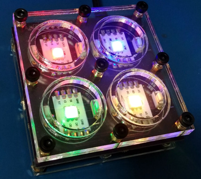
In the end, they cut the individual LEDs out of RGB strips, and soldered them down to their custom designed 500mmx500mm PCB. To the sides of each section of strip are two tactile switches, and above is a “sandwich” made of laser cut acrylic. The sheet closest to the LEDs has a 25mm hole, the top sheet has a 20mm hole, and between them is a circle of acrylic that acts as the “button”. Once it’s all screwed together, the button can’t fall out of the front or move from side to side, but it can be pushed down to contact the tactile switches.
To wire it all up they took a cue from the DIY keyboard scene and used a Teensy, some 595 shift registers, and 256 1N4148 diodes. A Raspberry Pi running their Python framework does the heavy computational lifting, leaving the Teensy to just handle talking to the hardware. Overall it’s a fantastic design to emulate if you’re looking to create large arrays of buttons on the cheap; such as whenever you get around to building that starship simulator.
With all due respect to the hackers and makers out there that provide us with all these awesome projects to salivate over, a good deal of them tend to prioritize functionality over aesthetics. Which isn’t a bad thing necessarily, and arguably better than the alternative. But for many people there’s a certain connotation around DIY, an impression that the final product is often a little rough around the edges. It’s usually cheaper, maybe even objectively better, but rarely more attractive.
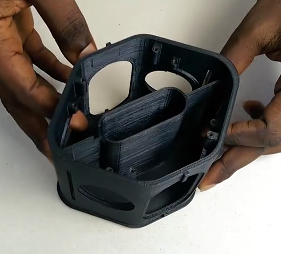
Which makes builds like this absolutely beautiful 3D printed Bluetooth speaker by [Ahmsville] especially impressive. Not only did he engineer a fantastic sounding speaker that projects stereo sound no matter where you are in the room, he clearly gave a lot of thought into making the final product look as good as it sounds.
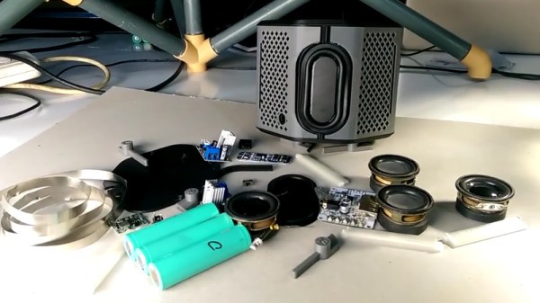
The 3D-printed enclosure provides separation for the four internal speakers and two passive radiators, as well as holding the electronics. A custom made 3S battery powers the Bluetooth module though an isolated step-down module, and the twin 18 W TDA2030 amplifiers feed their respective pair of drivers.
The device is surrounded by an impressively detailed 3D-printed mesh, which is then wrapped with some speaker grill fabric to give it a very professional look. In the video after the break, [Ahmsville] shows a time-lapse of building the speaker, as well as a demonstration of how it sounds on his desk.
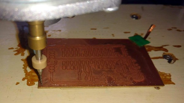
We know, we know. Getting PCBs professionally fabricated anymore is so cheap and easy that making them in-house is increasingly becoming something of a lost art. Like developing your own film. Or even using a camera that has film, for that matter. But when you’re in Brazil and it takes months for shipments to arrive like [Robson Couto] is, sometimes you’re better off sticking with the old ways.
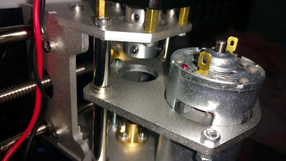
The primary hardware issues [Robson] ran into were in the Z axis, as some poor component selections made the stock configuration wobble a bit too much. He replaced some flimsy standoffs as well as swapping in some bushings he salvaged from dead inkjet printers, and the movement got a lot tighter.
Despite the fact that the version of Grbl flashed onto the engraver’s cloned Arduino Uno supports Z leveling, it’s not actually enabled out of the box. [Robson] just needed to add some extra wiring to use the spindle’s bit as a probe on the copper clad board. He also went ahead and updated to the latest version of Grbl, as the one which ships with the machine is fairly old.
There are many annoying issues associated with desktop 3D printers, but perhaps none are trickier than keeping the machine at the proper temperature. Too cold, and printed parts can warp or fail to adhere to the bed. Too hot, and the filament can get soft and jam, or the motors will start clanking and missing steps. High-end industrial 3D printers have temperature-controlled enclosures for precisely this reason, but the best you can hope for with a printer that’s little more than some aluminum extrusion and an Arduino is a heated bed that helps but is no substitute for the real thing.
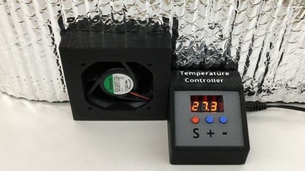
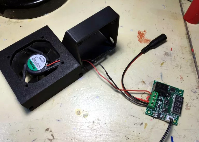
Like many 3D printer owners chasing perfect prints, [Steve Thone] ended up putting his machine into a DIY enclosure to help keep it warm. Unfortunately, there gets to be a point when things get a little too hot inside the insulating cube. To address this issue, he put together a simple but very elegant temperature controlled fan to vent the enclosure when the internal conditions go above the optimal temperature.
[Steve] picked up the digital temperature controller on Amazon for about $4 USD, and found a 60 mm fan in the parts bin. He then came up with a clever two-part printed enclosure that slides together to make the fan and controller one unit which he can place in a hole he cut in the enclosure.
A lot of attention was paid to the front panel of the device, including mid-print filament swaps to create highlighted text and separate buttons printed in different colors. The end result is a very professional looking interface that involved relatively little manual labor; often a problem when trying to come up with nice looking panels.
We’ve mentioned previously the challenges that come with maintaining vintage computers which in some cases are pushing 40 years old. Components, even high quality ones, eventually fail and need to be replaced. Now if it’s a fairly popular vintage machine, replacement parts usually aren’t too hard to come by. But what if you’re dealing with a machine that’s not just vintage, but was also such a commercial flop that parts are scarce?
Such is the life for anyone who owns one of the 500,000 IBM PCJrs that Big Blue managed to get out of the door during the year or so the product was on the market. As [AkBKukU] found, a replacement AC adapter for the odd-ball computer was going to cost more than what he paid for the thing, so he set to work on creating an adapter so he could use a modern ATX PSU on the machine. After a couple of months of ironing out the kinks, the design is finally ready for consumption.
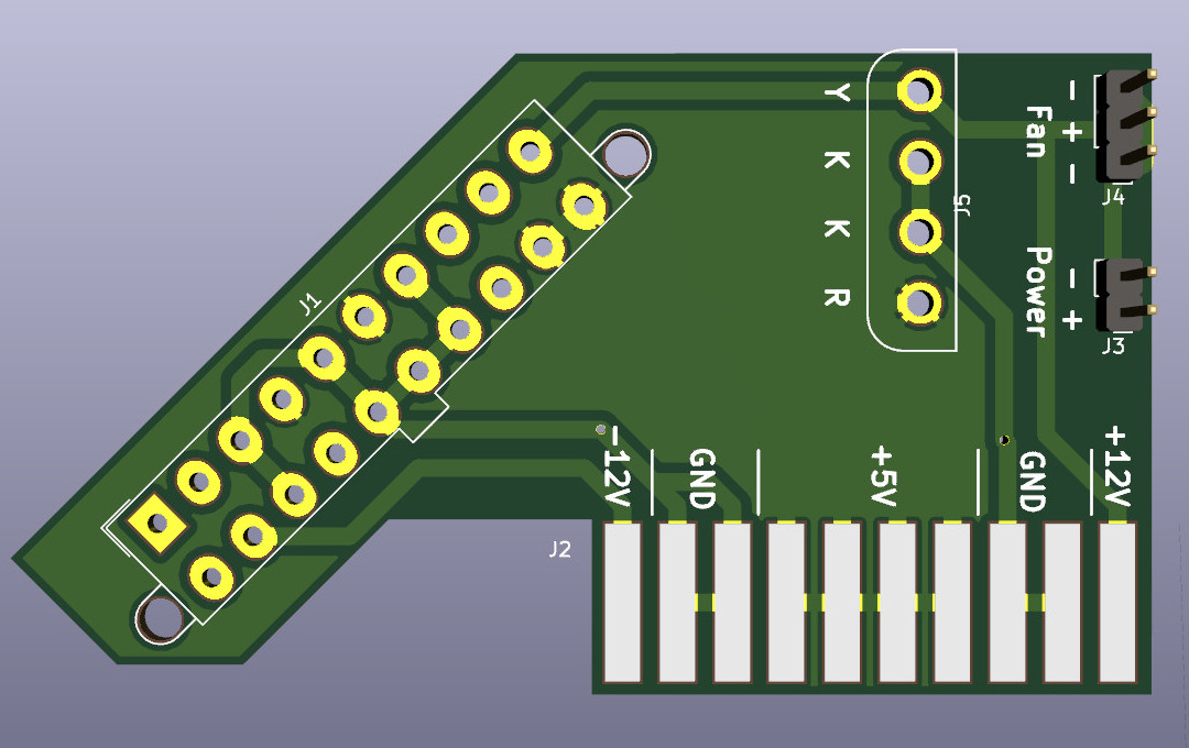
In the end, the PCB design itself is quite simple. It’s really just a matter of switching around some pins from the standard ATX plug to the edge connector on the PCJr. There’s also a connector for powering a floppy drive, as well as headers for a fan and power switch.
[AkBKukU] has come up with two ways to use the adapter. You can either go with a standard ATX PSU, in which case it will need to sit outside the machine due to its size, or use a PicoPSU which allows you to keep the whole thing internal. If you don’t mind spending the cash, the PicoPSU method is a much cleaner installation that still provides plenty of power. Depending on which route you take, there are different 3D printed plates to adapt the computer’s rear panel to fit the new hardware.

 Except, maybe not. When Japan Aerospace Exploration Agency (JAXA) launches their seventh Kounotori H-II Transfer Vehicle towards the International Space Station, riding along with the experiments and supplies for the astronauts, will be a very special pair of CubeSats. They make up the world’s first practical test of space elevator technology, and with any luck, will be one of many small steps that precedes the giant leap which access to space at a fraction of the cost will be.