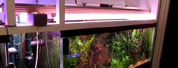
There’s an old saying that the cobbler’s children have no shoes. Sometimes we feel that way because we stay busy designing things for other people or for demos that we don’t have time to just build something we want. [Blue Blade Fish] wanted to build an Arduino-based aquarium controller. He’s detailed the system in (so far) 14 videos and it looks solid.
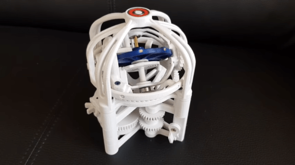
This isn’t just a simple controller, either. It is a modular design with an Arduino Mega and a lot of I/O for a serious fish tank. There are controls for heaters, fans, lights, wave makers and even top-off valves. The system can simulate moonlight at night and has an LCD display and keys. There’s also an Ethernet port and a Raspberry Pi component that creates a web interface, data storage, and configures the system. Even fail safes have been designed into the system, so you don’t boil or freeze expensive fishes. No wonder it took 14 videos!
Continue reading “Aquarium Controller Starring Arduino Gets A Long Video Description”