This year’s hottest new advance in electronics comes through wearable badges. You can’t have failed to notice another technology that’s getting really hot. It’s the blockchain. What is a blockchain? It’s a linked list where every item in the list contains a cryptographic hash of the previous item in the list. What is a blockchain in English? It’s the most revolutionary technology that’s going to solve every problem on the planet, somehow. It’s the basis for crypto (no not that one, the other one). The blockchain is how you add more Lamborghinis to your Lamborghini account. Even though we’re still trying to figure out how it solves a single problem, one thing is certain: blockchains solve every problem. We were born too late to explore the Earth, born too early to explore the Universe, but just in time for blockchain.
Independent badges are always looking at the latest technology, and perhaps this was inevitable. It’s a badge built on the blockchain. It’s a wearable sneakernet of mining. It’s a game with collaborative proof of work.
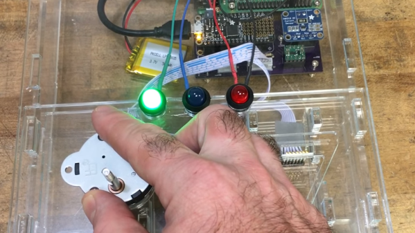
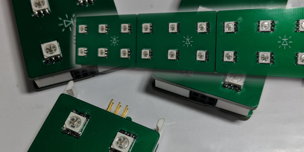
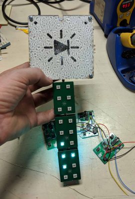 The blockchain badge from [Mr Blinky Bling] is an independent badge for this year’s Defcon, and like most independent badges it’s loaded up with RGB LEDs, microcontrollers, and exquisitely crafted FR4. What makes this badge different is the add-ons, or ‘blocks’ that attach to the main badge through 1/8″ phono jacks. These blocks form the basis of the social game, where two badge holders trade blocks for a while, allow their badges to perform a proof of work on each block, and finally, each block is hashed and the score increased. Yes, this is a blockchain, but it’s more of a block-tree, and it runs on sneakernet instead of the Internet.
Yes, this does indeed all sound like a joke. Make no mistake, though: this is real. This is a hardware game built on blockchain technology, that some lucky badge holders will be playing at this year’s Defcon. It’s filled with blinky and blockchain. It’s awesome.
[Mr. Blinky Bling] has already started a project for this badge over on hackaday.io, and right now they’re running a Kickstarter campaign for this badge with delivery at Defcon. This is one of the more interesting badges that will be floating around the con this year, and it has blockchain. This really isn’t one to miss.
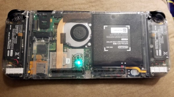
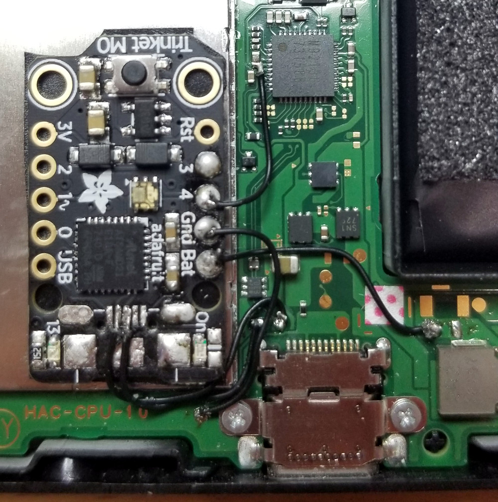

 The real treat here is [uli]’s


