First Look At DEF CON 26 Official Badge

To the delight of everyone, this year’s official DEF CON badge is an electronic badge chock full of entertainment. Of course there is blinky, the board is artistic, and everyone hopefully maybe gets one (it’s rumored 27,000+ were manufactured) if they don’t run out. But the badge contest at DEF CON is legendary — solve all the puzzles you are awarded the coveted black badge.

The creators of this badge are no strangers to the Hackaday community. Displayed proudly on the board and in the firmware, we discover that The Toymakers are the ones who have put it all on this line this year. Kudos to the dynamic hardware collective from Minnesota. There is no larger pressure cooker in the world of badges than this, and they pulled it off marvelously. Let’s take a look at all the goodies inside.

Most importantly, become a team member of the Hackaday.io DC26 badge solving project page to help discover all that’s involved in this badge. Okay, now let’s dive in!

Continue reading “First Look At DEF CON 26 Official Badge”

Results Of 3D-Printed Cylinder Head Testing Fail To Surprise

It’s the suburbanista’s weekend nightmare: you’re almost done with the weekly chores, taking the last few passes with the lawn mower, when you hear a pop and bang. The cylinder head on your mower just blew, and you’re out of commission. Or are you? You’ve got a 3D printer – couldn’t it save the day?

If this bench test of plastic cylinder heads is any indication, it’s possible – just as long as you’ve only got 40 seconds of mowing left to do. [Project Farm] has been running all sorts of tests on different materials as field-expedient cylinder heads for small gasoline engines, using everything from JB Weld epoxy to a slab of walnut. For this test, two chunky heads were printed, one from ABS, of the thermochromic variety apparently, the other in PLA. The test went pretty much as expected for something made of thermoplastic exposed to burning gasoline at high pressure, although ABS was the clear winner with two 40-second runs. The PLA only lasted half as long before the spark plug threads melted and the plug blew out. A gasket printed from flexible filament was also tested, with predictably awful results.

As bad as all this was, it still shows that 3D-printed parts are surprisingly tough. Each part was able to perform decently under a compression test, showing that they can stand up to pressure as long as there’s no heat. If nothing else, it was a learning experience. And as an aside, the cylinder heads were printed by [Terry] from the RedNeckCanadians YouTube channel. That video is worth a watch, if just for a few tips on making a 3D-printed copy of an object. Continue reading “Results Of 3D-Printed Cylinder Head Testing Fail To Surprise”

Hackaday guide to Lathes

Lathe Headstock Alignment: Cutting A Test Bar

Let’s say you’ve recently bought a lathe and set it up in your shop. Maybe you’ve even gone and leveled it like a boss. You’re ready to make chips, right? Well, not so fast. As real machinists will tell you, you can use all the levels and lasers and whatever that you want, but the proof is in the cut. Precision leveling gets your machine in the ballpark (machinists have very small ballparks) but the final step to getting a machine to truly perform well is to cut a test bar. This is a surefire way to eliminate any last traces of twist in the bed.

There are two types of test bars. One is for checking headstock-to-ways alignment, which is what we’re doing here. There’s another type used for checking tailstock alignment, but that’s a subject for another day.

Continue reading “Lathe Headstock Alignment: Cutting A Test Bar”

DIY Scientific Calculator Powered By Pi Zero

It’s the eternal question hackers face: do you built it, or do you buy it? The low cost and high availability of electronic gadgets means we increasingly take the latter option. Especially since it often ends up that building your own version will cost more than just buying a commercial product; and that’s before you factor in the time you’ll spend working on it.

But such concerns clearly don’t phase [Andrea Cavalli]. Sure he could just buy a scientific calculator, but it wouldn’t really be his scientific calculator. Instead, he’s taking the scenic route and building his own scientific calculator from scratch. The case is 3D printed, the PCB is custom, and even the software is his own creation.

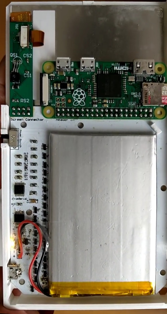
His PCB hooks right up to the GPIO pins of the internal Raspberry Pi Zero, making interfacing with the dome switch keyboard very easy. The board also holds the power management hardware for the device, including the physical power switch, USB connection for charging, and TPS79942DDCR linear regulator.

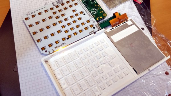
The case, including the buttons, is entirely 3D printed. At this point the buttons don’t actually have any labels on them, which presumably makes the calculator more than a little challenging to use, but no doubt [Andrea] is working on that for a later revision of the hardware. A particularly nice detail is the hatch to access the Pi’s micro SD card, making it easy to update the software or completely switch operating systems without having to take the calculator apart.

After the kernel messages scroll by, the Pi boots right into the Java calculator environment. This gives the user a fairly standard scientific calculator experience, complete with nice touches like variable highlighting. The Mario mini-game probably isn’t strictly required, but if you’re writing the code for your own calculator you can do whatever you want.

Here at Hackaday we’ve seen a calculator that got a Raspberry Pi upgrade, a classic scientific calculator emulated with an Arduino, and of course we’ve raved about the NumWorks open source graphing calculator. Even with such stiff competition, we think this project is well on its way to being one of the most impressive calculators we’ve ever come across.

Continue reading “DIY Scientific Calculator Powered By Pi Zero”

Learn FPGA Fast With Hackaday’s FPGA Boot Camp

FPGAs have gone from being a niche product for people with big budgets to something that every electronics experimenter ought to have in their toolbox. I am always surprised at how many people I meet who tell me they are interested in using FPGAs but they haven’t started. If you’ve been looking for an easy way to get started with FPGAs, Hackaday’s FPGA boot camp is for you. There’s even a Hackaday.io chat in the group specifically for FPGA talk for questions and general discussion!

While it is true FPGAs aren’t for everything, when you need them you really need them. Using FPGAs you can build logic circuits — not software simulations, but real circuits — and reap major performance benefits compared to a CPU. For digital signal processing, neural networks, or computer vision applications, being able to do everything essentially in parallel is a great benefit. Sometimes you just need the raw speed of a few logic gates compared to a CPU plodding methodically through code. We expect to see a lot more FPGA activity now that Arduino is in the game.

These boot camps gather together some of the material you seen spread over many articles here before, plus new material to flesh it out. It’s designed for you to work through more like a training class than just some text to read. There’s plenty of screenshots and even animations to help you see what you are supposed to be doing. You’ll be able to work with simulations to see how the circuits we talk about work, make changes, and see the results. We’ll focus on Verilog — at least for now — as it is close to C and easier for people who know C to pick up. Still not convinced? Let’s run though the gist of the boot camp series.

Continue reading “Learn FPGA Fast With Hackaday’s FPGA Boot Camp”

Rolling Out A Slick Rotary Phase Converter

Home machinists can often find great deals on used industrial equipment, and many a South Bend lathe or Bridgeport milling machine has followed someone home. Then comes the moment to plug it in, and the new owner discovers that the three-phase plug needed to power the new beast is nowhere to be found in the shop. Thus commences the weeping and the gnashing of teeth.

Luckily, [Handmade Extreme] is ahead of the curve in terms of shop power, and built a rotary phase converter to power his machines. Industry generally runs on three-phase AC systems, mainly because three-phase electric motors are so much more efficient and compact than the equivalent single-phase motor. But residential electrical service is either split-phase or, in the UK where [Handmade Extreme] is based, single phase. A rotary phase converter is an electromechanical device that can generate the missing phases – in essence a three-phase motor that can run on one winding and generate the missing phases across the other windings. It needs some supporting control circuitry to do so, such as timers and contactors to switch the winding connections once the motor starts, plus capacitors for motor starting and for balancing the voltage across the phases. The control gear is DIN-rail mounted and neatly wired to a smart-looking control panel. Everything is housed in a sturdy enclosure that’s big enough to serve as a mobile tool cart. It’s a really nice job – watch the whole build in the video below.

If you’re interested in power distribution, we’ve got a primer that covers the basics. And if you’re in the market for machine tools, [Quinn]’s machine tool buyer’s guide will let you decide if a three-phase machine is worth the extra effort.

Continue reading “Rolling Out A Slick Rotary Phase Converter”

Looking At Wind Turbines From A Different Angle

When we think of wind turbines, the first thing that usually comes to mind is the typical Sim City-esque type – 3 blades, gigantic, and wired into the municipal power grid. In truth, the world of wind power generation is far more varied indeed – as [Vittorio]’s vertical-axis wind turbine shows us.

So what exactly is a vertical-axis wind turbine, you ask? Well, rather than the typical setup with blades rotating about a horizontal axis, as in typical utility turbines or a classic electric fan you might use to cool off on a sunny day, instead a vertical axis is used. This necessitates a very different blade design due to the orientation of the rotational axis relative to the flow, so such turbines can be quite visually striking to those unfamiliar with such designs.

[Vittorio]’s design is a great way to get to grips with the type. The blades and supports were initially created out of PVC gutter channel, though 3D printed versions have also been developed. The motion is turned into electricity by using a simple brushed DC motor as a dynamo.

While the scale is small and the output only in the tens of watts, it goes to show that there’s always more than one way to do things.  We’ve seen some vertical-axis wind projects before, too. Video after the break.

Continue reading “Looking At Wind Turbines From A Different Angle”