The Eleven-Faced Die That Emulates Two Six-sided Dice

Rolling two six-sided dice (2d6) gives results from 2 to 12 with a bell curve distribution. Seven being the most common result, two and twelve being the least common. But what if one could do this with a single die?

This eleven-sided die has a distribution matching the results of 2d6.

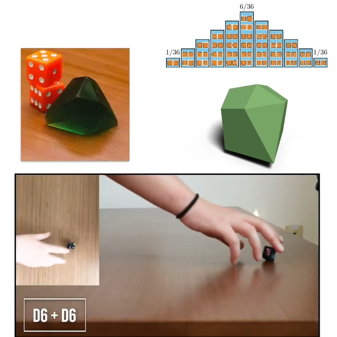
As part of research Putting Rigid Bodies to Rest, researchers show that a single eleven-sided asymmetric shape can deliver the same results. That is to say, it rolls numbers 2 to 12 in the same distribution as 2d6. It’s actually just one of the oddball dice [Hossein Baktash] and his group designed so if you find yourself intrigued, be sure to check out the 3D models and maybe print your own!

The research behind this is a novel method of figuring out what stable resting states exist for a given rigid body, without resorting to simulations. The method is differentiable, meaning it can be used not just to analyze shapes, but also to design shapes with specific properties.

For example, with a typical three-sided die each die face has an equal chance of coming up. But [Hossein] shows (at 8:05 in the video, embedded below) that it’s possible to design a three-sided die where the faces instead have a 25%-50%-25% distribution.

How well do they perform in practice? [Hossein] has done some physical testing showing results seem to match theory, at least when rolled on a hard surface. But we don’t think anyone has loaded these into an automated dice tester, yet.

Continue reading “The Eleven-Faced Die That Emulates Two Six-sided Dice”

Unusual Circuits In The Intel 386’s Standard Cell Logic

Intel’s 386 CPU is notable for being its first x86 CPU to use so-called standard cell logic, which swapped the taping out of individual transistors with wiring up standardized functional blocks. This way you only have to define specific gate types, latches and so on, after which a description of these blocks can be parsed and assembled by a computer into elements of a functioning application-specific integrated circuit (ASIC). This is standard procedure today with register-transfer level (RTL) descriptions being placed and routed for either an FPGA or ASIC target.

That said, [Ken Shirriff] found a few surprises in the 386’s die, some of which threw him for a loop. An intrinsic part of standard cells is that they’re arranged in rows and columns, with data channels between them where signal paths can be routed. The surprise here was finding a stray PMOS transistor right in the midst of one such data channel, which [Ken] speculates is a bug fix for one of the multiplexers. Back then regenerating the layout would have been rather expensive, so a manual fix like this would have made perfect sense. Consider it a bodge wire for ASICs.

Another oddity was an inverter that wasn’t an inverter, which turned out to be just two separate NMOS and PMOS transistors that looked to be wired up as an inverter, but seemed to actually there as part of a multiplexer. As it turns out, it’s hard to determine sometimes whether transistors are connected in these die teardowns, or whether there’s a gap between them, or just an artifact of the light or the etching process.

A Vintage Radiator Core, From Scratch

There are sadly few 1914 Dennis fire engines still on the road, so when the one owned by Imperial College in London needs a spare part, it can not be ordered from the motor factors and must be made from scratch. Happily, [Andy Pugh] is an alumnus with the required metalworking skills, so in the video below we see him tackling the manufacture of flattened brass tubes for its radiator core.

Forming a round tube to a particular shape is done by pulling it through a die whose profile gradually changes from round to the desired shape. We see him make a couple of tries at this, finally succeeding with one carefully designed to have a constant circumference. The use of CNC machining is something that wouldn’t have been available in the Dennis works in the early 20th century, so we can marvel at the skills of the machinists back then who made the original. Here in 2024 he makes a drawing rig with a geared chain drive suitable for larger scale production.

The video is both a fascinating look at tube drawing and a mind-cleansing piece of workshop observation, and we have to say we enjoyed watching it. If [Andy]’s name sounds familiar to you, this might be because this isn’t the first go he’s had at manufacturing vehicle parts.

Continue reading “A Vintage Radiator Core, From Scratch”

Laser Fault Injection, Now With Optional Decapping

Whether the goal is reverse engineering, black hat exploitation, or just simple curiosity, getting inside the packages that protect integrated circuits has long been the Holy Grail of hacking. It isn’t easy, though; those inscrutable black epoxy blobs don’t give up their secrets easily, with most decapping methods being some combination of toxic and dangerous. Isn’t there something better than acid baths and spinning bits of tungsten carbide?

[Janne] over at Fraktal thinks so, and the answer he came up with is laser decapping. Specifically, this is an extension of the laser fault injection setup we recently covered, which uses a galvanometer-scanned IR laser to induce glitches in decapped microcontrollers to get past whatever security may be baked into the silicon. The current article continues that work and begins with a long and thorough review of various IC packaging technologies, including the important anatomical differences. There’s also a great review of the pros and cons of many decapping methods, covering everything from the chemical decomposition of epoxy resins to thermal methods. That’s followed by specific instructions on using the LFI rig to gradually ablate the epoxy and expose the die, which is then ready to reveal its secrets.

The benefit of leveraging the LFI rig for decapping is obvious — it’s an all-in-one tool for gaining access and executing fault injection. The usual caveats apply, of course, especially concerning safety; you’ll obviously want to avoid breathing the vaporized epoxy and remember that lasers and retinas don’t mix. But with due diligence, having a single low-cost tool to explore the innards of chips seems like a big win to us.

Spinning Magnets Do Your Dice Rolling For You

Dice are about the simplest machines possible, and they’ve been used since before recorded history to generate random numbers. But no machine is so simple that a little needless complexity can’t make it better, as is the case with this mechanical spinning dice. Or die. Whatever.

Inspiration for the project came from [Attoparsec]’s long history with RPG and tabletop games, which depend on different kinds of dice to generate the randomness that keeps them going — that and the fortuitous find of a seven-segment flip-dot display, plus the need for something cool to show off at OpenSauce. The flip-dot is controlled by an array of neodymium magnets with the proper polarity to flip the segments to the desired number. The magnets are attached to an aluminum disk, with each array spread out far enough to prevent interference. [Attoparsec] also added a ring of magnets to act as detents that lock the disk into a specific digit after a spin.

The finished product ended up being satisfyingly clicky and suitably random, and made a good impression at OpenSauce. The video below documents the whole design and build process, and includes some design dead-ends that [Attoparsec] went down in pursuit of a multiple-digit display. We’d love to see him revisit some of these ideas, mechanically difficult though they may be. And while he’s at it, maybe he could spice up the rolls with a little radioactivity.

Continue reading “Spinning Magnets Do Your Dice Rolling For You”

photograph of custom PCB assembly of NE555-based electronic dice

NE555-Based Electronic Dice

It has become a bit of a running joke in the Hackaday community to suggest that a project could or should have been done with a 555 timer. [Tim] has rather taken this to heart with his latest Electronic Dice project, which uses three of the venerable devices.

If three seems like a lot of 555s to make an electronic die, then it may be worth considering that the last time we shared his project he was using 22 of them! Since then, [Tim] has been busy optimising his design, whilst keeping within the constraints of an old-school through-hole soldering kit.

Maybe the most surprising thing about this project is the purpose to which the NE555 devices are pressed. Rather than using them for their famous oscillation properties, they are in actual fact just being used as Schmitt Triggers to clean up the three-phase ring oscillator that is constructed from discrete transistors and passives.

scope trace of the electronic dice ring oscillator
Simulation trace of the three-phase ring oscillator before Scmitt Trigger stages

The ring oscillator cleverly produces three phase-shifted square waves such that a binary combination of the three phases offers six unique states. Six being the perfect number for a dice throw, all that then remains is to figure out which LEDs need to be switched on in which state and wire them up accordingly.

To “roll” the dice, a push-button powers up the oscillator, and stops it again when it is released, displaying the random end-state on the LEDs.

It can be fun to see what can be done using old technology, and educational to try to optimise a design down to the fewest parts possible.

[Tim]’s earlier project is here if you want to see how the design has evolved. The documentation on both of these iterations is excellent and well worth a read.

Continue reading “NE555-Based Electronic Dice”

Picture showing the way the cut-down piece of chip is soldered onto the mainboard - looking, indeed, like a QFN package.

Making A Handheld NES By Turning DIP Chips Into…QFN?

You can achieve a lot with a Dremel. For instance, apparently you can slim the original NES down into the hand-held form-factor. Both the CPU and the PPU (Picture Processing Unit) are 40-pin DIP chips, which makes NES minification a bit tricky. [Redherring32] wasn’t one to be stopped by this, however, and turned these DIP chips into QFN-style-mounted dies (Nitter) using little more than a Dremel cutting wheel. Why? To bring his TinyTendo handheld game console project to fruition, of course.

DIP chip contacts go out from the die using a web of metal pins called the leadframe. [Redherring32] cuts into that leadframe and leaves only the useful part of the chip on, with the leadframe pieces remaining as QFN-like contact pads. Then, the chip is mounted onto a tailored footprint on the TinyTendo PCB, connected to all the other components that are, thankfully, possible to acquire in SMD form nowadays.

This trick works consistently, and we’re no doubt going to see the TinyTendo being released as a standalone project soon. Just a year ago, we saw [Redherring32] cut into these chips, and wondered what the purpose could’ve been. Now, we know: it’s a logical continuation of his OpenTendo project, a mainboard reverse-engineering and redesign of the original NES, an effort no doubt appreciated by many a NES enthusiast out there. Usually, people don’t cut the actual chips down to a small size – instead, they cut into the mainboards in a practice called ‘trimming’, and this practice has brought us many miniature original-hardware-based game console builds over these years.

Continue reading “Making A Handheld NES By Turning DIP Chips Into…QFN?”