Relativity Space’s Quest To 3D Print Entire Rockets

While the jury is still out on 3D printing for the consumer market, there’s little question that it’s becoming a major part of next generation manufacturing. While we often think of 3D printing as a way to create highly customized one-off objects, that’s a conclusion largely based on how we as individuals use the technology. When you’re building something as complex as a rocket engine, the true advantage of 3D printing is the ability to not only rapidly iterate your design, but to produce objects with internal geometries that would be difficult if not impossible to create with traditional tooling.

SpaceX’s SuperDraco 3D Printed Engine

So it’s no wonder that key “New Space” players like SpaceX and Blue Origin make use of 3D printed components in their vehicles. Even NASA has been dipping their proverbial toe in the additive manufacturing waters, testing printed parts for the Space Launch System’s RS-25 engine. It would be safe to say that from this point forward, most of our exploits off of the planet’s surface will involve additive manufacturing in some capacity.

But one of the latest players to enter the commercial spaceflight industry, Relativity Space, thinks we can take the concept even farther. Not content to just 3D print rocket components, founders Tim Ellis and Jordan Noone believe the entire rocket can be printed. Minus electrical components and a few parts which operate in extremely high stress environments such as inside the pump turbines, Relativity Space claims up to 95% of their rocket could eventually be produced with additive manufacturing.

If you think 3D printing a rocket sounds implausible, you aren’t alone. It’s a bold claim, so far the aerospace industry has only managed to print relatively small rocket engines; so printing an entire vehicle would be an exceptionally large leap in capability. But with talent pulled from major aerospace players, a recently inked deal for a 20 year lease on a test site at NASA’s Stennis Space Center, and access to the world’s largest metal 3D printer, they’re certainly going all in on the idea. Let’s take a look at what they’ve got planned.

Continue reading “Relativity Space’s Quest To 3D Print Entire Rockets”

Homemade Shop Vise Packs A Hydraulic Punch

It’s a sad day when one of the simplest and generally most reliable tools in the shop – the bench vise – gives up the ghost. With just a pair of beefy castings and a heavy Acme screw, there’s very little to go wrong with a vise, but when it happens, why not take it as an opportunity to make your own? And, why not eschew the screw and go hydraulic instead?

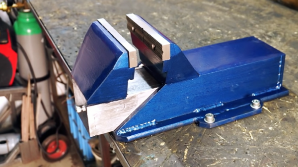
That’s the path [Darek] plotted when his somewhat abused vise reached end-of-life with an apparently catastrophic casting failure. His replacement is completely fabricated from steel bar and channel stock, much of it cut on his nifty plasma cutter track. The vice has a fixed base and rear jaw, with a moving front jaw. Hiding inside is a 5-ton single-acting hydraulic cylinder. A single acting cylinder won’t open the vise on its own, so [Darek] came up with a clever return mechanism: a pair of gas springs from a car trunk.

With a pair of hardened steel jaws, some modifications to the power cylinder to allow foot operation, and a spiffy paint job, the vise was ready for service. Check out the build in the video below; we’re impressed with the power the vise has, and hands-free operation is an unexpected bonus.

Yes, most people buy vises, but from the small to the large, it’s nice to see them built from scratch too.

Continue reading “Homemade Shop Vise Packs A Hydraulic Punch”

How Precise Is That Part? Know Your GD&T

How does a design go from the computer screen to something you hold in your hand? Not being able to fully answer this question is a huge risk in manufacturing because . One of the important tools engineers use to ensure success is Geometric Dimensioning and Tolerancing (GD&T).

A good technical drawing is essential for communicating your mechanical part designs to a manufacturer. Drafting, as a professional discipline, is all about creating technical drawings that are as unambiguous as possible, and that means defining features explicitly. The most basic implementation of that concept is dimensioning, where you state the distance or angle between features. A proper technical drawing will also include tolerances for those dimensions, and I recently explained how to avoid the pitfall of stacking those tolerances.

Dimensions and tolerances alone, however, don’t tell the complete story. On their own, they don’t specify how closely the geometric form of the manufactured part needs to adhere to your perfect, nominal representation. That’s what we’re going to dig into today with GD&T.

Continue reading “How Precise Is That Part? Know Your GD&T”

Scooter Hauls Kids With A Little Heavy Metal

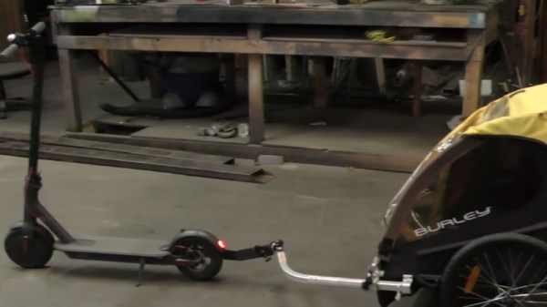
Where there’s a will, there’s a way. Similarly, where there’s a paying customer and a well stocked metalworking shop, there will also be a way. That’s about all the backstory you need to understand this latest creation from [Richard Day] of 42Fab. A customer asked him to build something that didn’t exist, and in a few hours he not only fabricated it from scratch but documented the whole thing for our viewing pleasure.

The object in question is a mount that would allow the customer to pull a “Burley Bee” kid trailer behind their electric scooter. The trailer is only meant for a bicycle, but the expected stresses of getting pulled around by a scooter seemed similar enough that [Richard] figured it should work. Especially since the ride height of the scooter lined up almost perfectly with the trailer’s tongue. The trick is, he wanted to avoid making permanent changes to either the scooter or the trailer.

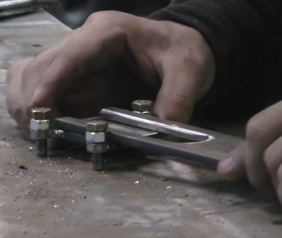
On the scooter side, [Richard] came up with a clamp arrangement that would squeeze onto the frame. This gave him plenty of strength, without having to put any holes in the scooter. To create the clamp he took two pieces of 1/4″ x 2″ steel flat bar and welded 5/16″ nuts to them. By drilling the threads out of outer nuts they act as bushings, so cranking down on the bolts draws the two pieces together. To simplify the alignment, he welded the nuts to the bars while the bolts were threaded in, so he knew everything would be in place.

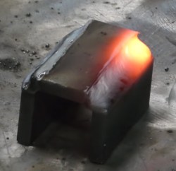
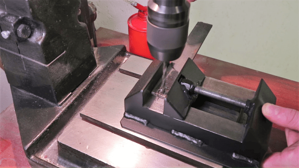
For the trailer side, he took another piece of flat steel and turned it into a “U” shape by cutting almost all the way through the back of it and then folding it over in his vice. A bead of metal was then laid in the cut with the welder to strengthen it back up. [Richard] used this opportunity to demonstrate the difference between pushing and pulling the torch while welding, which is an interesting tip to file away. A hole drilled through the two sides and a little grinding, and it’s ready to mount.

Between the two fabricated components is some flat stock welded at an eyed up angle. As [Richard] says in the video, the nice thing about these one-off projects is that you can basically design on the fly. Plus you can always use a hammer to make some final adjustments.

While his isn’t the first bike trailer hack we’ve seen here at Hackaday, it would be fair to say it’s something of a rarity around these parts. Usually we get word of somewhat larger bits of kit getting dragged around.

Continue reading “Scooter Hauls Kids With A Little Heavy Metal”

A Scratch-Built Drill Press Vise From Scrap

Never underestimate the importance of fixturing when you’re machining parts. No matter what the material, firmly locking it down is the key to good results, and may be the difference between a pleasant afternoon in the shop and a day in the Emergency Room. Flying parts and shattered tooling are no joke, but a lot of times quality commercial solutions are expensive and, well, commercial.  So this scratch-built drill press vise is something the thrifty metalworker may want to consider.

To be sure, [Ollari’s] vise, made as it is almost completely from scrap angle iron, is no substitute for a vise made from precision ground castings. But it’s clear that he has taken great care to keep everything as square and true as possible, and we give him full marks for maximizing his materials. And his tools — nothing more complicated than a MIG welder is used, and most of the fabrication is accomplished with simple hand tools. We like the way he built up sturdy profiles by welding strap stock across the legs of the angle iron used for the jaws, to give them a strong triangular cross-section to handle the clamping force. And using the knurled end of an old socket wrench as the handle was inspired; we’ll certainly be filing that idea away for a rainy day in the shop. Although we might use Acme rather than plain threaded rod.

We always enjoy seeing someone fabricate their own tools, and this one reminds us a bit of the full-size bench vise built up from layers of welded steel we featured a while back. It even looks a little like this 3D-printed vise, too.

Continue reading “A Scratch-Built Drill Press Vise From Scrap”

A CNC Woodworking Tool That Does The Hard Parts

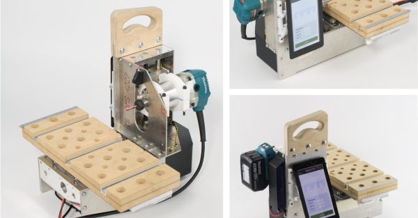
Drawn along in the wake of the 3d printing/home shop revolution has been the accessibility of traditional subtractive CNC equipment, especially routers and mills. Speaking of, want a desktop mill? Try a Bantam Tools (née Othermachine) Desktop Milling Machine or a Carvey or a Carbide 3D Nomad. Tiny but many-axis general purpose mill? Maybe a Pocket NC. Router for the shop? Perhaps a Shapeoko, or an X-Carve, or a ShopBot, or a… you get the picture. [Rundong]’s MatchSticks device is a CNC tool for the shop and it might be classified as a milling machine, but it doesn’t quite work the way a more traditional machine tool does. It computer controls the woodworker too.

Sample joints the MatchSticks can cut

At a glance MatchSticks probably looks most similar to a Pocket NC with a big Makita router sticking out the side. There’s an obvious X-axis spoilboard with holes for fixturing material, mounted to a gantry for Z-axis travel. Below the big friendly handle on top is the router attached to its own Y-axis carriage. The only oddity might be the tablet bolted to the other side. And come to think of it the surprisingly small size for such an overbuilt machine. What would it be useful for? MatchSticks doesn’t work by processing an entire piece of stock at once (that what you’re for, adaptable human woodworker) it’s really a tool for doing the complex part of the job – joinery – and explaining to the human how to do the rest.

The full MatchSticks creation flow goes like this:

  1. Choose a design to make on the included interface and specify the parameters you want (size, etc).
  2. The MatchSticks tool will suggest what material stocks you need, and then ask you to cut them to size and prepare them using other tools.
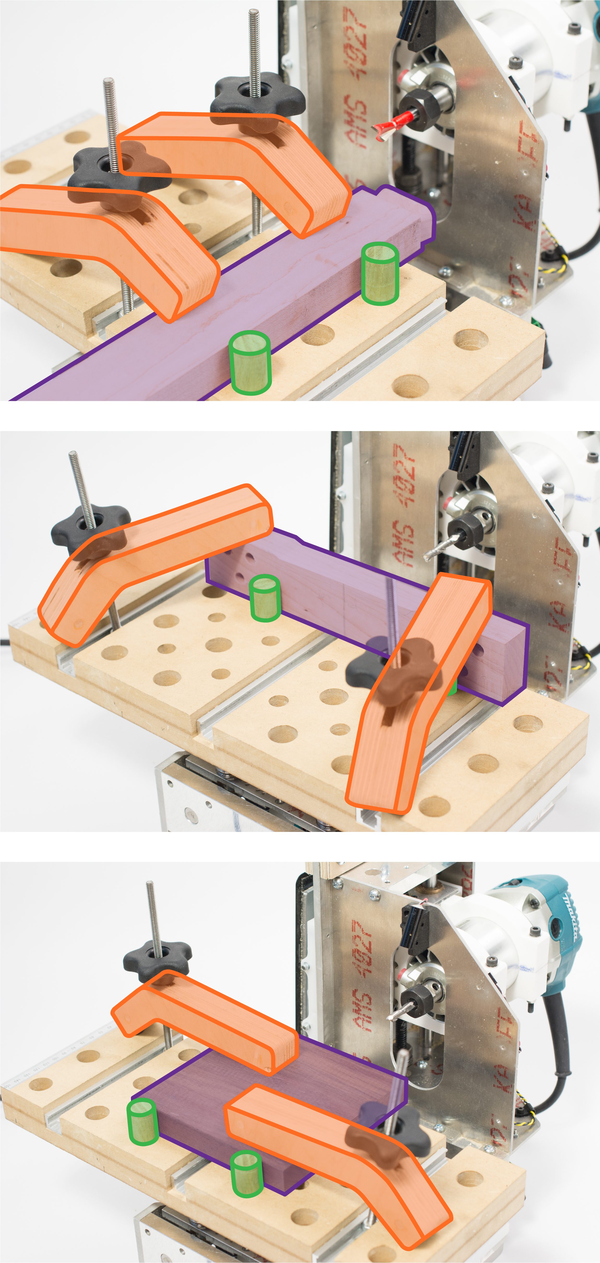
  3. For any parts which require CNC work the tool will help guide the user to fixture the stock to its bed, then do the cutting itself.
  4. Once everything is ready for final assembly the MatchSticks will once again provide friendly instructions for where to pound the mallet.

In this way [rundong], [sarah], [jeremy], [ethan], and [eric] were able to build a much smaller machine tool without sacrificing much practical functionality. It’s almost software-like in it’s focus on a singular purpose. Why reinvent what the table saw can do when the user probably already has access to a table saw that will cut stock better? MatchSticks is an entire machine bent around one goal, making the hard stuff easier.

It’s worth noting that MatchSticks was designed as an exploration into computer/human interaction for the ACM Conference on Human Factors in Computing Systems so it’s not a commercial product quite yet (we’re eagerly waiting!). For a much more in depth look at the project and its goals and learnings the full research paper is available here. Their intro video is down after the break.

Thanks [ethan] for the tip!

Continue reading “A CNC Woodworking Tool That Does The Hard Parts”

DIY Tube Oven Brings The Heat To Homebrew Semiconductor Fab

Specialized processes require specialized tools and instruments, and processes don’t get much more specialized than the making of semiconductors. There’s a huge industry devoted to making the equipment needed for semiconductor fabrication plants, but most of it is fabulously expensive and out of reach to the home gamer. Besides, where’s the fun in buying when you can build your own fab lab stuff, like this DIY tube oven?

A tube oven isn’t much more complicated than it sounds — it’s just a tube that gets hot. Really, really hot — [Nixie] is shooting for 1,200 °C. Not just any materials will do for such an oven, of course, and this one is built out of blocks of fused alumina ceramic. The cavity for the tube was machined with a hole saw and a homebrew jig that keeps everything aligned; at first we wondered why he didn’t use his lathe, but then we realized that chucking a brittle block of ceramic would probably not end well. A smaller hole saw was used to make trenches for the Kanthal heating element and the whole thing was put in a custom stainless enclosure. A second post covers the control electronics and test runs up to 1,000°C, which ends up looking a little like the Eye of Sauron.

We’ve been following [Nixie]’s home semiconductor fab buildout for a while now, starting with a sputtering rig for thin-film deposition. It’s been interesting to watch the progress, and we’re eager to see where this all leads.