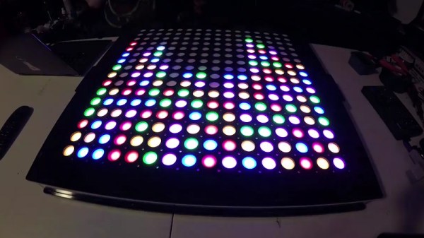
Bixel, An Open Source 16×16 Interactive LED Array

The phrase “Go big or go home” is clearly not lost on [Adam Haile] and [Dan Ternes] of Maniacal Labs. For years they’ve been thinking of creating a giant LED matrix where each “pixel” doubled as a physical push button. Now that they’ve built up experience working on other LED projects, they finally decided it was time to take the plunge and create their masterpiece: the Bixel.

Creating the Bixel (a portmanteau of button, and pixel) was no small feat. The epic build is documented in an exceptionally detailed write-up on the team’s site, in addition to the time-lapse video included after the break. [Adam] tells us the Bixel took around 100 hours of assembly, and we don’t doubt it. This is truly one of those labors of love which is unlikely to be duplicated, though all of the source files for both the hardware and software are available if you’re feeling brave enough.

The write-up contains a lot of fascinating detail about the design and construction of the Bixel, but perhaps the least surprising of all of them is that the final product ended up being very different from what they originally envisioned. The plan was to simply use lighted arcade buttons in a 16×16 grid, as they were purpose-built for exactly what the guys had in mind. But when they priced them out, the best they could do was $2 a pop. That’s $500 for just the buttons alone, before they even got into the enclosure or electronics. Like any good hackers, [Adam] and [Dan] decided to ditch the ready-made solution and come up with something of their own.

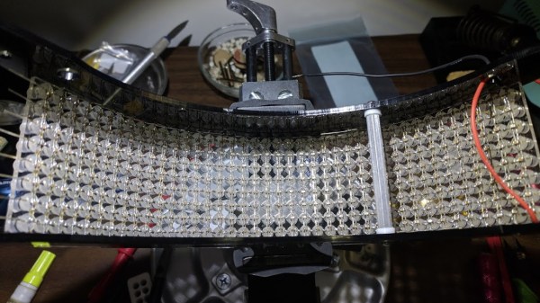
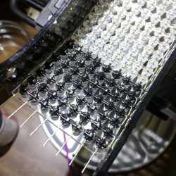
In the end, they cut the individual LEDs out of RGB strips, and soldered them down to their custom designed 500mmx500mm PCB. To the sides of each section of strip are two tactile switches, and above is a “sandwich” made of laser cut acrylic. The sheet closest to the LEDs has a 25mm hole, the top sheet has a 20mm hole, and between them is a circle of acrylic that acts as the “button”. Once it’s all screwed together, the button can’t fall out of the front or move from side to side, but it can be pushed down to contact the tactile switches.

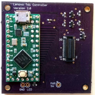
To wire it all up they took a cue from the DIY keyboard scene and used a Teensy, some 595 shift registers, and 256 1N4148 diodes. A Raspberry Pi running their Python framework does the heavy computational lifting, leaving the Teensy to just handle talking to the hardware. Overall it’s a fantastic design to emulate if you’re looking to create large arrays of buttons on the cheap; such as whenever you get around to building that starship simulator.

Continue reading “Bixel, An Open Source 16×16 Interactive LED Array”

Sad Without A SID? This Comes Pretty Close

The MOS Technologies 6851, popularly known as the SID, is a legendary sound synthesiser integrated circuit from the early 1980s that is most famous for providing the Commodore 64 home computer with its ability to make noise. At the time it was significantly better than what could be found in competitor machines, making it a popular choice for today’s chiptune and demo scene artists.

There’s a snag for a modern-day SID-jockey though, the chip has been out of production for a quarter century and is thus in short supply. Emulation is a choice, but of little use for owners of original hardware so it’s fortunate that [Petros Kokotis] has produced a SID replacement using a Teensy 3.6.

The operation is simple enough, the Teensy provides all the requisite SID data lines via some level shifters for the host microcomputer, and uses [Frank Boesing]’s ReSID library to do the heavy lifting part of being a SID. You can download the code from a GitHub repository, and he’s posted a video we’ve put below the break showing a prototype in action with a real Commodore 64. The audio quality isn’t brilliant due to a phone camera recording from a very tinny speaker, but notwithstanding that it has the air of the real thing.

This isn’t the first SID we’ve seen here. How about a MIDI synth using one?

Continue reading “Sad Without A SID? This Comes Pretty Close”

Mademoiselle Pinball Table Gets Rock ‘n Roll Makeover

Once upon a time, there was a music venue/artist collective/effects pedal company that helped redefine industry in Williamsburg, Brooklyn. That place was called Death By Audio. In 2014, it suffered a death by gentrification when Vice Media bought the building that DBA had worked so hard to transform. From the ashes rose the Death By Audio Arcade, which showcases DIY pinball cabinets made by indie artists.

Their most recent creation is called A Place To Bury Strangers (APTBS). It’s built on a 1959 Gottlieb Mademoiselle table and themed around a local noise/shoegaze band of the same name that was deeply connected to Death By Audio. According to [Mark Kleeb], this table is an homage to APTBS’s whiz-bang pinball-like performance style of total sensory overload. Hardly a sense is spared when playing this table, which features strobe lights, black lights, video and audio clips of APTBS, and a fog machine. Yeah.

[Mark] picked up this project from a friend, who had already cut some wires and started hacking on it. Nearly every bit of the table’s guts had to be upgraded with OEM parts or else replaced entirely. Now there’s a Teensy running the bumpers, and another Teensy on the switches. An Arduino drives the NeoPixel strips that light up the playfield, and a second Uno displays the score on those sweet VFD tubes. All four micros are tied together with Python and a Raspi 3.

If you’re anywhere near NYC, you can play the glow-in-the-dark ball yourself on July 15th at Le Poisson Rouge. If not, don’t flip—just nudge that break to see her in action. Did we mention there’s a strobe light? Consider yourself warned.

Want to get into DIY pinball on a smaller scale? Build yourself a sandbox and start playing.

Continue reading “Mademoiselle Pinball Table Gets Rock ‘n Roll Makeover”

Homebrew SDR Ham Radio In 9 Parts

It used to be homebrew ham gear meant something simple. A couple of active devices that could send CW. Maybe a receiver with a VFO. But only the most advanced builders could tackle a wide range SSB transceiver. Today, that goal is still not trivial, but it is way easier due to specialty ICs, ready access to high-speed digital signal processing, and advances in software-defined radio techniques. [Charlie Morris] decided to build an SSB rig that incorporated these technologies and he shared the whole process from design to operation in a series of nine videos. You can see the first one below.

The NE612 is a child of the popular NE602 chip, which contains a Gilbert-cell mixer, and an oscillator that makes building a receiver much easier than it has been in the past. The chips are set up as direct conversion receivers and feed a Teensy which does the digital signal processing on the recovered audio.

Continue reading “Homebrew SDR Ham Radio In 9 Parts”

Hacked RC Transmitters Control All The Things

If you have lots of RC creations about, each with their own receiver, you’ll know that the cost of a new one for each project can quickly mount up – despite RC receivers being pretty cheap these days. What if you could use a NRF24L01+ module costing less than $3?

That’s just what [Rudolph] has done for his Hackaday Prize entry, rudRemoteThough many people already spin their own RC link with the NRF24 modules, this sets itself apart by being a complete, well thought out solution, easily scalable to a large number of receivers.

The transmitter can be made of anything to hand; stick an NRF24 module and Teensy inside, some gimbals if needed, and you have a rudRemote transmitter. Gaming controllers, sandwich boxes and piles of laser cut parts are all encouraged options. [Rudolph] used some 40-year-old transmitters for his build – on the outside they remain unchanged, apart from a small OLED and rotary encoder for the function menu. The gimbal connections are simply re-routed to the Teensy I/O.

The protocol used is CRTP (Crazy RealTime Protocol); this is partly because one of the things [Rudolph] wanted to control is a CrazyFlie quadcopter. It’s a protocol that can easily be used to control anything you like, providing it fits into the 29-byte payload space. The CrazyFlie only uses 14 bytes of that, so there’s plenty of headroom for auxiliary functions.

We’d be interested to see the latency of this system – we’ve some surprising results when it comes to measuring cheap RC transmitter latency.

Vintage Organ Donates Parts For Two New Instruments

It’s often hard to know what to do with a classic bit of electronics that’s taking up far too much of the living room for its own good. But when the thing in question is an electronic organ from the 1970s, the answer couldn’t be clearer: dissect it for its good parts and create two new instruments with them.

Judging by [Charlie Williams]’ blog posts on his Viscount Project, he’s been at this since at least 2014. The offending organ, from which the project gets its name, is a Viscount Bahia from the 1970s that had seen better days, apparently none of which included a good dusting. With careful disassembly and documentation, [Charlie] took the organ to bits. The first instrument to come from this was based on the foot pedals. A Teensy and a custom wood case turned it into a custom MIDI controller; hear it in action below. The beats controller from the organ’s keyboard was used for the second instrument. This one appears far more complex, not only for the beautiful, hand-held wooden case he built for it, but because he reused most of the original circuitry. A modern tube amp was added to produce a little distortion and stereo output from the original mono source, with the tip of the tube just peeking above the surface of the instrument. We wish there were a demo video of this one, but we’ll settle for gazing at the craftsmanship.

In a strange bit of timing, [Elliot Williams] (no relation, we assume) just posted an Ask Hackaday piece looking for help with a replacement top-octave generator for another 1970s organ. It’s got a good description of how these organs worked, if you’re in the mood to learn a little more.

Continue reading “Vintage Organ Donates Parts For Two New Instruments”

Glow In The Dark Globe On A Spherical Screen

Terrestrial globes are almost a thing of the past in an era of Google Earth, but they can still be an exciting object worth hacking together, as [Ivan Miranda] shows with his glow-in-the-dark globe. It’s a globe, it’s a display, and it’s a great use of glow in the dark filament.

For the mechanical part of this build, [Miranda] used glow in the dark filament to 3D print a sphere and a reinforcing ring that hides inside. A threaded rod through the middle secured with screws and bearings make an appropriate spindle, and is attached to a stepper motor in the 3D printed stand. So far, it’s a sphere made of glowey plastic. Where’s the ‘globe’ part coming from?

To project a globe onto this sphere, [Miranda] used a strip of WS2812B LEDs stuck to the inside of the stand’s arc are programmed to selectively illuminate the globe as it rotates on its axis. After a brief hiccup with getting the proper power supply, he was ready to test out his new….. giant light ball.

It turns out, the filament was a bit more transparent than he was expecting so he had to pull it all apart and cover the interior with aluminium tape. [Miranda] also took the chance to clean up the wiring, code, and upgrade to a Teensy 3.1 before another test.

Despite the resulting continental projection being upside-down, it worked! [Miranda] added a USB cable before he closed it up again in case he wanted to reprogram it and display any number of images down the line.

[Thanks for the tip, olivekrystal!]