555 Timer On Its Own In Electronic Dice

One of the most common clichés around here is that a piece of equipment chosen for a project is always too advanced. If a Raspberry Pi was used, someone will say they should have used an Arduino. If they use an Arduino, it should have been an ATtiny. And of course, if an ATtiny was used, there should have simply been a 555 timer. This time, however, [Tim] decided to actually show how this can be done by removing some of the integrated circuits from an electronic dice and relying entirely on the 555 timer for his build.

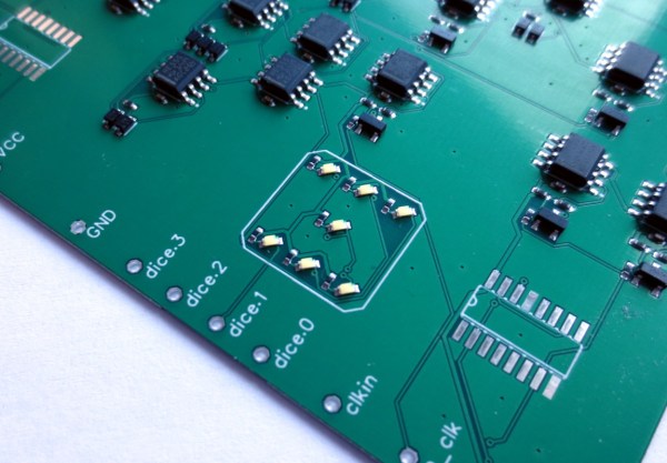
The electronic dice that [Tim] has on hand makes use of two main ICs: a NE555 and a CD4017 which is a decade counter/divider used for cycling through states. In order to bring the 555 to the forefront of this build, he scraps the CD4017 and adds an array of 555 timers. These are used to generate the clock signals necessary for this build but can also be arranged to form logic circuits. This comes at a great cost, however. The 555 chips take up an unnecessarily large area on the PCB (even though these are small surface-mount chips), consume an incredible amount of power, and are very slow. That’s fine for an electronic dice-rolling machine like this one, but that’s probably where [Tim] will leave this idea.

The 555 timer is a surprisingly versatile chip, and this project shows that there is some element of truth to the folks claiming that projects need naught but a few 555s. We’ve seen entire CPUs built using nothing but 555s, and even a classic project that uses a 555 timer to balance a robot.

Significantly Improved Egg Timer Makes Pictionary Better

The traditional sand timer, known colloquially as an egg timer, served its purpose well over the centuries since its development. However, [MakerPaul] realised it had some significant flaws that were ruining Pictionary, and set out to fix the problem.

If you’re not looking directly at an egg timer, it’s easy to miss the moment when the timer runs out. Resetting the timer before it runs out also requires waiting for the sand to filter to one side. Clearly the world needs a better mousetrap.

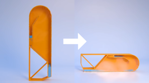
The tipping timer from [MakerPaul] solves both those issues. In this design, sand flows down into an offset area, which tips the device over when reaching a certain time limit. Additionally, turning the device upside down and then rotating it instantly reloads the sand, meaning the timer can be reused immediately.

[MakerPaul] first came up with the idea about 20 years ago, refining it during the recent lockdowns. The design files are freely available for anyone that wishes to build one. [MakerPaul] isn’t commercializing the idea, but mentions that it would be great if anyone using it makes a donation to the Mind mental health charity.

Most timers we feature are electronic and digital, but it’s easy to appreciate the elegance of what [MakerPaul] has achieved here. As a bonus, he documented the entire project and its application in under 90 seconds. How good is that? Video after the break.

Continue reading “Significantly Improved Egg Timer Makes Pictionary Better”

Minimalist Timer Counts Down With LED Matrix

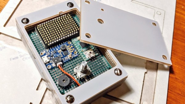
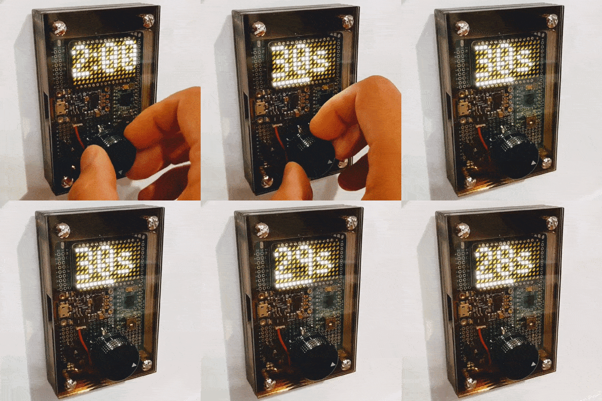
Looking for something with a bit more style than the traditional kitchen timer, [Martin Jonasson] decided to take the last couple of months to design and build his own take on the idea using a rotary encoder, 16×9 LED matrix, and a Teensy 2.0 microcontroller. Were there better things he could have spent that time on? Possibly. But you probably wouldn’t have been reading it about it here, so we won’t trouble ourselves with such thoughts.

Put together on a piece of perfboard, the handwired circuit also includes an Adafruit PowerBoost 500 Charger, a 3.7 V 2500 mAh LiPo battery, a IS31FL3731 Charlieplexed PWM LED driver, and a piezo buzzer. The top of the rotary encoder has been capped off with a sold metal knob, which combined with the enclosure made of stacked laser cut 3 mm acrylic sheets, really gives the device a very sleek and classy look.

While the hardware is quite nice, it’s the software that really pulls this whole project together. A game developer by trade, [Martin] went all in on the timer’s GPLv3 licensed firmware. From using the toneAC library to play melodies at the end of the countdown, to the custom fonts and the code that pauses the timer while the user is spinning the knob, there’s plenty of little touches that should make the timer a joy to use. We’ve seen some unique kitchen timers over the years, but the attention to detail put into this build really raises the bar.

[Martin] has provided everything you need to create your own version of his timer, including the SVG file for the laser cut case. While not strictly required, coming up with a custom PCB for this project would be a nice touch, should you want to put your own spin on it.

[Thanks to Tom for the tip.]

Mickey’s Big Timer Makes Glider Competitions Better

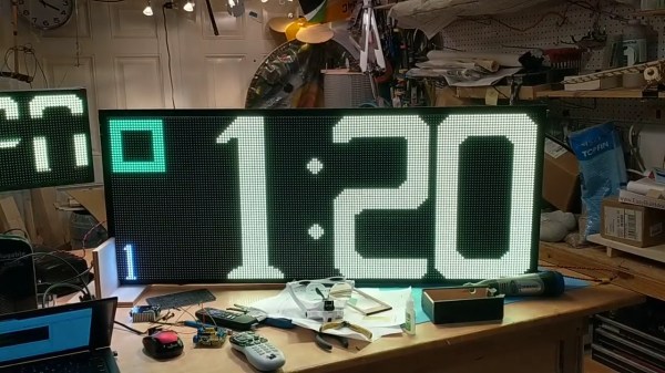
There’s plenty of obscure sports in the world. Many of them could benefit from bespoke equipment like scoring displays, but are too obscure to support commercial efforts in this regard. Radio controlled glider competitions fit into just this category. This led a man named [Mickey] to develop what he calls Mickey’s Big Timer, to aid in the running of such events.

Glider events run outdoors in full sunlight, so the system uses big bright LED matrix displays to show its timing information. The system, built around the STM32 Discovery platform, uses several of the microcontroller boards to drive several displays as well as the main controller which handles timing. It also packs in an audio system for issuing instructions to competitors. It can also display pilot names as well as instructions such as when competitors should land at the end of a heat.

Some code is available on Github for those interested in how it all works. Word around the RC forums has it that [Mickey] built several systems, some of which ended up as far afield as New Zealand where they helped run many successful glider contests over the years.

We’ve seen plenty of scoreboard projects over the years; a little portable one could be useful for adding some spice to your pickup neighbourhood games. Video after the break.

Continue reading “Mickey’s Big Timer Makes Glider Competitions Better”

Should Have Used A Vacuum Tube 555

“You should have used a 555” has become a bit of a meme around these parts lately, and for good reason. There seems to be little that these ubiquitous chips can’t be used for, and in a world where code often substitutes for hardware, it’s easy to point to instances where one could have just used a simple timer chip instead.

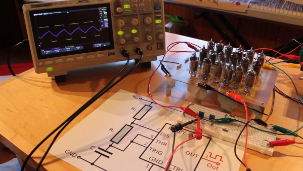
Definitely not in the meme category, though, is this overkill vacuum tube 555 timer. It comes to us via [David Lovett], aka [Usagi Electric], who has lately caught the “hollow state” electronics bug and has been experimenting with all sorts of vacuum tube recreations of circuits we’re far more used to seeing rendered in silicon than glass. The urge to replicate the venerable 555 in nothing but vacuum tubes is understandable, as it uses little more than a pair of comparators and a flip-flop, circuits [David] has already built vacuum tube versions of. The only part left was the discharge transistor; a pentode was enlisted to stand in for that vital function, making the circuit complete.

To physically implement the design, [David] built a large PCB to hold the 18 vacuum tubes and the handful of resistors and capacitors needed. Mounted on eight outsized leads made from sheet steel, the circuit pays homage to the original 8-pin DIP form of the 555. The video below shows the design and build process as well as testing of all the common modes of operation for the timer chip.

You can check out more of our coverage of [David]’s vacuum tube adventures, which started with his reverse-engineering of an old IBM logic module. And while he did a great job explaining the inner workings of the 555, you might want to take a deeper dive into how the venerable chip came to be.

Continue reading “Should Have Used A Vacuum Tube 555”

Arduino Wannabe Should Have Used A 555. Oh Wait, It Does.

It’s a little known secret that when the Hackaday writers gather in their secret underground bunker to work on our plans for world domination, we often take breaks to play our version of the corporate “Buzzword Bingo”, where paradigms are leveraged and meetings circle back to loop in offline stakeholders, or something like that. Our version, however, is “Comment Line Bingo”, and right in the middle of the card is the seemingly most common comment of all: “You should have used a 555,” or variations thereof.

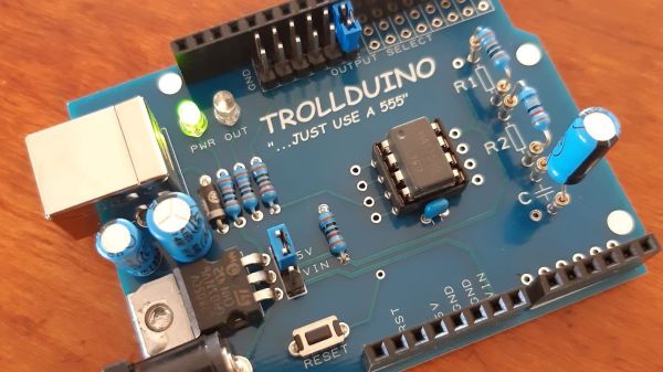
So it was with vicious glee that we came across the Trollduino V1.0 by the deliciously named [Mild Lee Interested]. It’s the hardware answer to the common complaint, which we’ll grant is often justified. The beautiful part of this is that Trollduino occupies the same footprint as an Arduino Uno and is even pin-compatible with the microcontroller board, or at least sort of. The familiar line of components and connectors sprout from the left edge of the board, and headers for shields line the top and bottom edges too. “Sketches” are implemented in hardware, with jumpers and resistors and capacitors of various values plugged in to achieve all the marvelous configurations the indispensable timer chip can be used for. And extra points for the deliberately provocative use of Comic Sans in the silkscreen.

Hats off to [Lee] for a thoroughly satisfying troll, and a nice look at what the 555 chip can really do. If you want a more serious look at the 555, check out this 555 modeled on a breadboard, or dive into the story of the chip’s development.

Bare-Metal STM32: Blinky And The Secret Of Delay Functions

One of the very first examples for an MCU or SoC usually involves the famous ‘Blinky‘ example, where an LED is pulsed on and off with a fixed delay. This is actually a lot more complicated than the ‘Pushy‘ example which we looked at in the first installment of this series. The reason for this is that there’s actually quite a story behind a simple call to delay() or its equivalent.

The reason for this is that there are many ways to implement a delay function on a microcontroller (MCU), each of which comes with their own advantages and disadvantages. On an STM32 MCU, we get to choose between essentially an active delay (while loop), one implemented using the SysTick timer and using one of the peripheral timers. In the latter two cases we also have to use interrupts.

In this article we’ll take a look at all three approaches, along with their advantages and disadvantages.

Continue reading “Bare-Metal STM32: Blinky And The Secret Of Delay Functions”