[Ben Eater]’s Breadboarding Tips

A solderless breadboard is a place where ideas go to become real for the first time. Usually, this is a somewhat messy affair, with random jumpers flying all about the place, connecting components that can be quickly swapped to zero in on the right values, or to quickly change the circuit topology. Breadboards aren’t the place to make circuit artwork.

That is, however, not always the case, and we’ve seen more than a few examples from [Ben Eater] on breadboarding that approaches the circuit sculpture level of craftsmanship. And like any good craftsman, [Ben] has shared some of his breadboarding tips and tricks in a new video. Starting with a simple 555 blinkenlight project that’s wired up in the traditional anything-goes fashion, [Ben] walks us through his process for making a more presentation-worthy version.

His tools are high-quality but simple, with the wire strippers being the most crucial to good results. Surprisingly, [Ben] relies most heavily on the simple “scissors-style” strippers for their versatility, rather than the complicated semi-automatic tools. We found that to be the biggest take-home from the video, as well as the results of practice. [Ben] has done tons of this type of breadboarding before, which means when he “eyeballs” stripping 0.3 inches of insulation, he can do it down to a ten-thousandth precision.

Granted, there’s not much new here, but watching this video is a little like watching [Bob Ross] paint — relaxing and strangely compelling at the same time. You can get more of the same with pretty much any of his videos that we’ve covered, like this 6502 breadboard computer build. We’ve also seen [Eater]-inspired builds that are pretty impressive, like this full-8-bit breadboard computer.

Continue reading “[Ben Eater]’s Breadboarding Tips”

DIY Cable Chain Looks Great, Stays Cheap

If you’ve built a 3D printer, CNC, laser cutter, or basically any piece of electrical equipment that moves around, then you’ve run into the problem of securing the bundle of wires that such machines always require. The easy way out is to zip tie them all up into a tight harness or put them in commercially available wraps or sleeves, but these don’t really impart any mechanical strength on the wires. With repetitive motion it’s not unheard of to break a conductor or two, causing intermittent failures and generally leading to a painful diagnostic session trying to isolate the broken wire.

An alternative are what are generally referred to as “cable chains”. These are rigid enclosures for your wiring that not only keep things tidy, but give the wires the mechanical support necessary to prevent fatigue. Unfortunately, they are often many times more expensive than a simple wire wrap or pack of zip ties. But [Brad Parcels] has written into our tip line to share with us a sort of hybrid approach to wire management that has many of the same advantages as a traditional cable chain, but at a greatly reduced cost.

The key to the design is using the metallic tape from a cheap tape measure to give the bundle of wires some mechanical strength. As anyone who’s ever played around with a tape measure knows, if you bend the tape over into a U shape it will hold the bend even if you extend and retract it. Thanks to this principle, [Brad] realized that all he need to do was add some wire sleeves and he would have a cheap and effective way to keep his wiring neat and sag-free.

[Brad] punches holes in the tape to secure it to his 3D printed mounting arms, but really any method of securing the tape to the frame of your machine will work just as well. He then slides a cable sleeve over the tape itself to protect from any possibility of the edge of the tape nicking a wire, and then finally a larger wire sleeve over the entire assembly.

After running the wires between the two sleeves, heatshrink can be used on the ends to neatly close everything up. Just make sure you remember all your wires before you seal it, [Brad] learned that one the hard way. But overall, he reports this DIY cable chain arrangement has been working wonderfully in his machine, providing smooth and silent movement for only a few bucks.

Cable management for projects that move is one of those things that doesn’t always get the attention it deserves. Not only can it keep your project looking professional, but it just might save you some time down the road by preventing failures.

Tips For Basic Machining On A Drill Press

It’s safe to say most Hackaday readers would love to have a mill at home, or a nice lathe, but such equipment isn’t always practical for the hobbyist. The expense and amount of room they take up is a hard sell unless you’re building things on them regularly, so we’re often forced to improvise. In his latest video, [Eric Strebel] gives some practical advice on using a standard drill press to perform tasks you would normally need a mill or lathe for; and while his tips probably won’t come as a surprise to the old-hands out there, they might just help some of the newer players get the most out of what they have access to.

[Eric] explains the concept of the cross slide vice, which is the piece of equipment that makes machining on a drill press possible. Essentially it’s a standard vice, but with screws that allow you to move the clamped piece in the X and Y dimensions under the drill which can already move in the Z dimension. For those counting along at home, that puts us up to the full three dimensions; in other words, you can not only make cuts of varying depths, but move the cut along the surface of the work piece in any direction.

You can even turn down a (small) piece of round stock by placing it in the chuck of the drill press, and putting a good chisel in the cross slide vice. The chisel can then be moved up against the spinning piece to make your cuts. We don’t suggest doing anything too heavy, but if you need to turn down something soft like a piece of plastic or wood to a certain diameter, it can do in a pinch.

[Eric Strebel] is quickly becoming a favorite around these parts. His well-produced videos show viewers the practical side of product design and in-house manufacturing. We recently covered his video on doing small-scale production, and there’s plenty more invaluable info to be had browsing back through his older videos.

The quest to do machining without actually having a machine shop is certainly not new to Hackaday. There have been many different approaches to solving the issue, but picking up a decent drill press and cross slide is a first step down the rabbit hole for most people.

Continue reading “Tips For Basic Machining On A Drill Press”

Go From Resin Caster To Resin Master

When it comes to resin casting, time is of the essence. It helps to gather everything you’ll need and have it within reach before starting. But if you don’t know what you don’t know, it can be difficult to anticipate needs. Luckily, [Botzen Design] has a few tricks up his sleeve that will save time, materials, and sanity for novices and old hands alike.

It may seem somewhat obvious to mix up resin in a disposable or reusable plastic cup. But not all cups are created equal. Polypropylene cups won’t outgas into your resin, but polystyrene will. If you use a silicone cup or any polypropylene food container marked #5/PP, cured resin will peel cleanly off of the cup walls.

For some reason, the giant jugs of resin [Botzen Design] uses don’t come with pumps. How do they expect someone to meter out exact amounts of resin and hardener while pouring them out of gallon jugs? Stadium-style condiment pumps at a restaurant supply store make things much simpler while avoiding costly spillage.

Our favorite tip (and seemingly [Botzen Design]’s as well) is the drip hammer. When air bubbles mature into craters, they can be filled easily and precisely with a drop or two of wet resin. A pipette would probably just get clogged, but an icicle of cured resin hanging from a stick makes the perfect drip applicator.

Want to get into resin casting but don’t know where to start? Hackaday’s own [Gerrit] has you more than covered.

Continue reading “Go From Resin Caster To Resin Master”

Sacrificial Bridge Avoids 3D Printed Supports

[Tommy] shares a simple 3D printing design tip that will be self-evident to some, but a bit of a revelation to others: the concept of a sacrificial bridge to avoid awkward support structures. In the picture shown, the black 3D print has small bridges and each bridge has a hole. The purpose of these bits is to hold a hex nut captive in the area under the bridge; a bolt goes in through the round hole in the top.

Readers familiar with 3D printing will see right away that printing the bridges might be a problem. When a printer gets to the first layer of the bridge, it will be trying to lay filament in empty space. By itself this is not usually a problem as long as a bridge is short, flat, and featureless. Unfortunately this bridge has a hole in it, and that hole means the printer will be trying to draw circles in mid-air, rather than simply stretching filament point-to-point across a gap. One solution would be to add a small amount of support structure, but that just moves the problem. Removing small supports from enclosed spaces can be a real hassle.

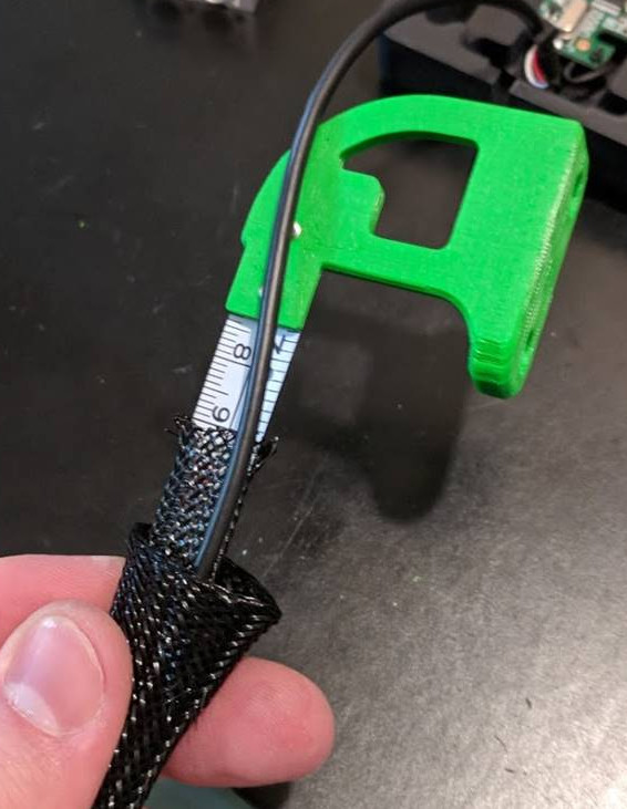
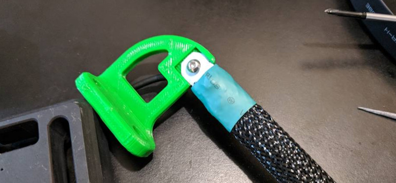
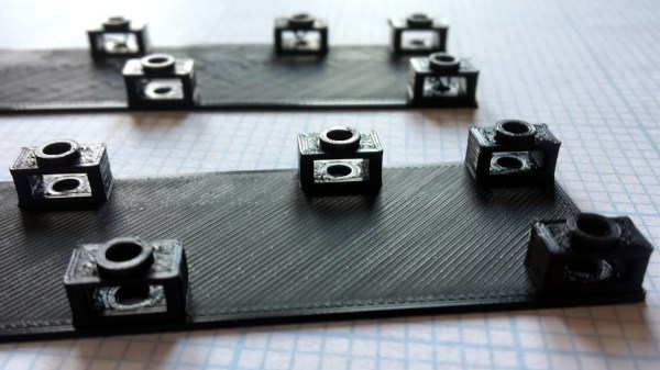
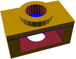
To solve this [Tommy] added what he calls a “sacrificial bridge”, shown as blue in the CAD image. He essentially gives the hole a flat bottom, so that the printer first lays down a thin but solid bridge as a foundation. Then, the portion with the round hole is printed on top of that. With this small design change, the print becomes much more reliable with no support structure required.

There is a bit of post-work involved since each hole needs to be drilled out to punch through the thin sacrificial bridge underneath, but it definitely beats digging out little bits of support structure instead.

The Little Things I Didn’t Know About Small DC Motors

We’ve all taken apart a small toy and pulled out one of those little can motors. “With this! I can do anything!” we proclaim as we hold it aloft. Ten minutes later, after we’ve made it spin a few times, it goes into the drawer never to be seen again.

It’s all their fault

It always seems like they are in everything but getting them to function usefully in a project is a fool’s errand. What the heck are they for? Where do people learn the black magic needed to make them function? It’s easy enough to pull out the specification sheet for them. Most of them are made by or are made to imitate motors from the Mabuchi Motor Corporation of Japan. That company alone is responsible for over 1.5 billion tiny motors a year.

More than Just the Specs

In the specs, you’ll find things like running speed, voltage, stall current, and stall torque. But they offer anything but a convincing application guide, or a basic set of assumptions an engineer should make before using one. This is by no means a complete list, and a skip over the electrics nearly completely as that aspect of DC motors in unreasonably well documented.

The paint mixers high running speed and infrequent use make it a decent candidate for hooking directly to the motor.

The first thing to note is that they really aren’t meant to drive anything directly. They are meant to be isolated from the actual driving by a gear train. This is for a lot of reasons. The first is that they typically spin very fast, 6,000 – 15,000 rpm is not atypical for even the tiniest motor. So even though the datasheet may throw out something impressive like it being a 3 watt motor, it’s not exactly true. Rather, it’s 3 N*m/s per 15,000 rotations per minute motor. Or a mere 1.2 milliwatt per rotation, which is an odd sort of unit that I’m just using for demonstration, but it gives you the feeling that there’s not a ton of “oomph” available. However, if you start to combine lots of rotations together using a gear train, you can start to get some real power out of it, even with the friction losses.

The only consumer items I can think of that regularly break this rule are very cheap children’s toys, which aren’t designed to last long anyway, and those powered erasers and coffee stirrers. Both of these are taking for granted that their torque needs are low and their speed needs are high, or that the motor burning out is no real loss for the world (at least in the short term).

This is because the motors derate nearly instantly. Most of these motors are hundreds of loops of very thin enameled wire wrapped around some silicon steel plates spot welded or otherwise coerced together. This means that even a small heat event of a few milliseconds could be enough to burn through the 10 micrometer thick coating insulating the coils from each other. Practically speaking, if you stall a little motor a few times in a row you might as well throw it away, because there’s no guessing what its actual performance rating is anymore. Likewise, consistently difficult start-ups, over voltage, over current, and other abuse can quickly ruin the motor. Because the energy it produces is meant to spread over lots of rotations, the motor is simply not designed (nor could it be reasonably built) to produce it all in one dramatic push.

Making Contact

Pololu has the clearest picture of the different kind of brushes inside these small motors.

This brings me to another small note about these tiny motors. Most of them don’t have the carbon brushes one begins to expect from the more powerful motors. Mostly they have a strip of copper that’s been stamped to have a few fingers pressing against the commutator. There’s lots of pros to these metal contacts and it’s not all cost cutting, but unless you have managed to read “Electrical Contacts” by Ragnar Holm and actually understood it, they’re hard to explain. There’s all sorts of magic. For example, just forming the right kind of oxide film on the surface of the commutator is a battle all on its own.

It’s a weird trade off. You can make the motor cheaper with the metal contacts, for one. Metal contacts also have much lower friction than carbon or graphite brushes. They’re quieter, and they also transfer less current, which may seem like a bad thing, but if you have a stalled motor with hairlike strands transferring the pixies around the last thing you’d want to do is transfer as much current as possible through them. However, a paper thin sheet of copper is not going to last very long either.

So it comes down to this, at least as I understand it: if bursts of very fast, low energy, high efficiency motion is all that’s required of the motor over its operational life then the metal strip brushes are perfect. If you need to run the motor for a long stretches at a time and noise isn’t an issue then the carbon brush version will work, just don’t stall it. It will cost a little bit more.

Take Care of Your Tiny Motors

Here is one of these can motors being restrained properly. Only torque on the case itself is restrained. The motor is otherwise free to move.
Here is one of these motors being restrained properly. Only torque on the case is restrained. The motor is otherwise free to move.

To touch one other small mechanical consideration. They are not designed to take any axial load at all, or really even any radial load either. Most of them have a plastic or aluminum bronze bushing, press-fit into a simple stamped steel body. So if you design a gearbox for one of these be sure to put as little force as possible on the bearing surfaces. If you’ve ever taken apart a small toy you’ve likely noticed that the motor can slide back and forth a bit in its mounting. This is why.

Lastly, because most of these motors are just not intended to run anywhere near their written maximum specifications it is best to assume that their specifications are a well intentioned but complete lie. Most designs work with the bottom 25% of the max number written on the spreadsheet. Running the motor anywhere near the top is usually guaranteed to brick it over time.

These are useful and ubiquitous motors, but unlike their more powerful cousins they have their own set of challenges to work with. However, considering you can buy them by the pound for cheaper than candy, there’s a good reason to get familiar with them.

Tips For Buying Your First Milling Machine

If you’re interested in making things (and since you’re reading this, we’re going to assume you are), you’ve almost certainly felt a desire to make metal parts. 3D printers are great, but have a lot of drawbacks: limited material options, lack of precision, and long printing times. If you want metal parts that adhere to even moderately tight tolerances, a milling machine is your only practical option. There is, after all, a very good reason that they’re essential to manufacturing.

However, it can be difficult to know where to start for the hobbyist who doesn’t have machining experience. What kind of milling machine should you get? Should you buy new or used? What the heck is 3-phase power, and can you get it? These questions, among many others, can be positively overwhelming to the uninitiated. Luckily, we — your friends at Hackaday — are here to help give you some direction. So, if you’re ready to learn, then read on! Already an expert? Leave some tips of your own in the comments!

Continue reading “Tips For Buying Your First Milling Machine”