As amazing as CircuitPython is, it hasn’t yet been ported to any 8-bit microcontrollers. [Chris Heo] was unsatisfied with his inability to use Python on his 8-bit ATmega4808 AVR, so he worked out a way to zombify it and bend it to his will using Python on his PC.
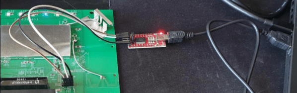
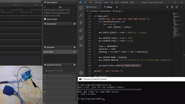
The trick to making this all work is the UPDI interface: a single-wire UART interface for programming and debugging Microchip’s newer 8-bit AVR microcontrollers. UPDI reaches deep into the microcontroller’s core, allowing you to stop and start execution of microcontroller code and access all of the onboard data and I/O. [Chris] realized this could be used to stop execution of any code running on the AVR and directly control the output pins using the pyupdi library. Since UPDI lets him modify the AVR’s I/O registers, he was also able to blink an LED and use the microcontrollers UART to send a message back to his PC without compiling a single line of code.
This may seem like an entirely unnecessary hack, but for devices too small or basic to have a JTAG interface for debugging this could be the best way to test and debug peripherals in an assembled circuit. We hope this catches on and would love to see how much of the chip can be controlled in this way. Maybe this will make it easy to experiment with the programmable logic that’s on some of the newer AVRs.